Front fuel oil purifying device of engine and application of front fuel oil purifying device

An engine and fuel technology, which is applied to engine components, combustion engines, machines/engines, etc., can solve problems such as high cost, damage, clogging of three-way catalytic converters, etc., so as to reduce the generation of carbon deposits, reduce pollution, and reduce excessive exhaust gas. The effect of emissions

Inactive Publication Date: 2016-01-06
蔚敬
View PDF7 Cites 0 Cited by
  • Summary
  • Abstract
  • Description
  • Claims
  • Application Information

AI Technical Summary

Problems solved by technology

However, the cost of the existing three-way catalytic converter is high. When the oil product is not good, the fuel components will be sintered and crystallized, which will easily lead to the blockage and damage of the three-way catalytic converter.

Method used


Image

  • Front fuel oil purifying device of engine and application of front fuel oil purifying device
  • Front fuel oil purifying device of engine and application of front fuel oil purifying device
  • Front fuel oil purifying device of engine and application of front fuel oil purifying device

Examples


Embodiment 1

[0034] Embodiment 1: Tin-antimony alloy adsorption catalytic element

[0035] The raw materials for preparation are solid tin and antimony, which are melted into liquid at a high temperature of 300 degrees, mixed according to the ratio through a 1200 degrees vacuum furnace, and copper accounting for 3% of the mass of tin and antimony is added at the same time. The shape of the grid is an open steel mold, and the liquid Pour on the mold and make a circular outer cylinder and a middle grid shape through cold water cooling. The diameter (outer diameter) of the circle is 26mm, such as Figure 5 , Figure 6 , the tin-antimony alloy catalytic element 5 is a structure in which a tin-antimony alloy mesh is placed horizontally in a circular outer cylinder. There are square meshes 6 on the tin-antimony alloy mesh, and the size of the mesh is 2.5×2.5; the distance between adjacent meshes is mm. The height of the circular outer cylinder is 5mm, and the thickness of the horizontal tin-ant...

Embodiment 2

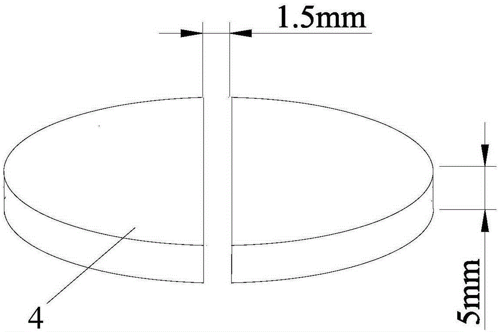
[0038]Two semicircular NdFeB magnets form a group, with a diameter of 25mm and a thickness of 5mm. The N pole and S pole face the same direction, and the distances between the centers of the two semicircles are 1.5mm, 3mm, and 4mm respectively. . Use the WT10A Gauss meter to measure the magnetic field strength between the two semicircles, which are 8800 Gauss, 7000 Gauss and 6500 Gauss respectively. Therefore, the distance between the centers of the two semicircles in the device for pre-purifying fuel oil designed by the present invention is 1.5 mm. Such as figure 1 .

Embodiment 3

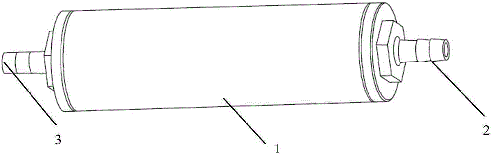
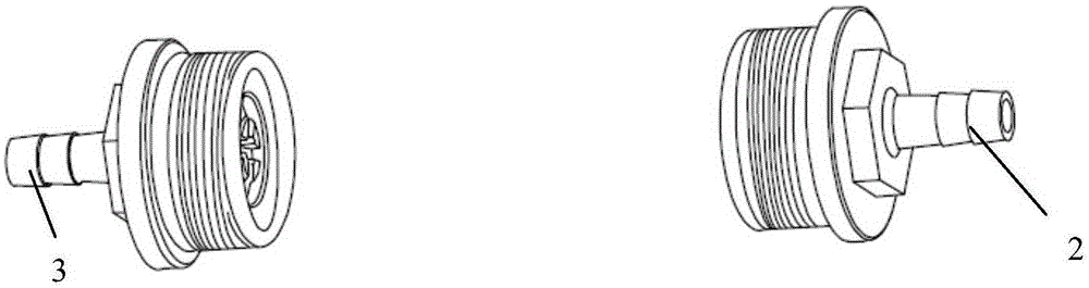
[0040] see Figure 2 to Figure 4 . A device for purifying fuel oil at the front of the engine. The shell of the device is a shell 1 in the shape of a circular tube. The two ends of the circular tube are respectively the oil inlet 2 and the oil outlet 3. In the shell of the alumina tube, 8 sets of NdFeB magnets are placed alternately. sheet and 9 tin-antimony alloy catalytic elements 5; the outer diameter of the shell is 38mm, and the length (not including the oil inlet and oil outlet) is 160mm. The NdFeB magnet sheet 4 is in the shape of a semicircle, two semicircular NdFeB magnet sheets form a group, the N pole and the S pole face the same direction, and the distance between the centers of the two semicircles is 1.5mm;

[0041] see Figure 7 There is a built-in sleeve 7 (PVC material) in the shape of a hollow tube in the shell of the fuel purification device. The inner wall of the sleeve is provided with radially opposite protrusions, and two semicircular NdFeB magnets are ...


PUM


Abstract

The invention provides a front fuel oil purifying device of an engine. A device shell is in the shape of a circular pipe. An oil inlet and an oil outlet are formed in the two ends of the circular pipe respectively. Neodymium iron boron magnet sheets and tin-antimony alloy catalyst elements are arranged in the shell. The neodymium iron boron magnet sheets are in a semicircular shape, every two semi-circular neodymium iron boron magnet sheets serve as one group, the poles N and the poles S of the neodymium iron boron magnet sheets are in the same direction to form a magnetic field, and the distance between the circle centers of every two semicircles ranges from 1 mm to 4 mm. The tin-antimony intermetallic compound serves as a medium, sulphur in gasoline is removed, and therefore the content of sulphur in the gasoline is reduced. Multiple vertical sets are manufactured through high-performance high-magnetism neodymium iron boron, in the fuel oil flowing process, the fuel oil passes a gap between two semicircular magnets, a cluster in the fuel oil is cut and scattered, and the fuel oil entering the engine is high in quality and good in atomization and is burned more sufficiently. Meanwhile, emission of oxynitride, CO and HC is reduced, the automobile tail gas pollution is generally reduced, and the atmosphere pollution is reduced.

Description

technical field [0001] The invention belongs to the field of engines, and in particular relates to a purification device arranged on an automobile engine and its application. Background technique [0002] With the development of science and technology and the improvement of people's living standards, the number of automobiles in my country is increasing at an annual growth rate of 9%, while the tail gas emitted by the combustion of automobile fuel is causing more and more serious air pollution in large and medium-sized cities. In order to control air quality, many countries have proposed control standards for vehicle exhaust emissions, including CO (carbon monoxide), HC (hydrocarbons), NOx (nitrogen oxides), and PM (particulate, soot) emission upper limits. To reduce tail gas pollution, it is more effective to carry out purification treatment from the fuel link than tail gas treatment. [0003] About 80% of gasoline in my country comes from fluid catalytic cracking (FCC), w...

Claims


Application Information

Patent Timeline
Patent Type & Authority Applications(China)
IPC IPC(8): F02M27/02F02M27/04F02M37/22F01N3/28F01N3/08
CPCY02A50/20Y02T10/12
Inventor 蔚敬
Owner 蔚敬
Why Eureka
Try Eureka