Pivoting foot platform for elliptical apparatus

a technology of elliptical apparatus and platform, which is applied in the field of elliptical cycle foot platform, can solve the problems of limiting the range of viable foot platform angles, putting undue stress on the knee and ankle joints of the rider, and extreme foot platform angles that are uncomfortable for the rider, so as to reduce the overall length of the elliptical cycle frame and reduce weight and cos

Active Publication Date: 2018-07-03
PT MOTION WORKS INC
View PDF9 Cites 2 Cited by
  • Summary
  • Abstract
  • Description
  • Claims
  • Application Information

AI Technical Summary

Benefits of technology

[0007]An aspect of the invention involves a pivoting foot platform on a rear-drive elliptical cycle. The pivoting foot platform allows for the use of a shorter drive arm than would be possible with a fixed foot platform to achieve a desired generally elliptical or ovate foot path. The shorter drive arm enables a reduction in the overall length of the elliptical cycle's frame with a corresponding reduction in weight and cost.
[0009]For a rear-drive elliptical cycle, the foot path is determined by the drive arm length, the foot platform position on the drive arm, the crank arm length, the rocker arm length (if a rocker crank mechanism) and the crank pivot offset from the reciprocating axis. Adjusting one or more of these factors will change the foot path. The ideal design usually involves setting these factors to provide the most comfortable and power-efficient foot path possible while minimizing the size of the frame.
[0010]Human anatomy limits the range of foot angles that are viable for powering an elliptical cycle. Extreme foot platform angles can be uncomfortable for the elliptical cycle rider. If the angle is too extreme at the top of the power stroke, it can put undue stress on the rider's knee and ankle joints. If the angle is too extreme at the bottom of the power stroke, it can aggravate the rider's Achilles tendon. Over time, either of these extremes can lead to injuries. For a rear-drive elliptical cycle with fixed foot platforms attached directly to the drive arm, the pedal angle during the pedal stroke is determined by the drive arm angle. In turn, the drive arm angle during the pedal stroke is directly related to the length of the drive arm, the length of the crank arm to which it is attached and the crank pivot offset from the reciprocating axis. For a given crank arm length and crank pivot offset, shortening the drive arm increases the drive arm angles at both the top and bottom of the power stroke. For a given crank arm length and drive arm length, reducing the crank pivot offset decreases the drive arm angles at both the top and bottom of the power stroke. As a result, for elliptical cycles with rigid platforms, there is a minimum drive arm length that is viable for a given crank arm length and crank pivot offset. By using a pivoting foot platform, this minimum drive arm length can be shortened because the angle of the elliptical cycle rider's foot is decoupled from the angle of the drive arm. This enables the rider to dynamically determine his foot angle throughout the pedal stroke and choose a comfortable angle when the drive arm angle at either the top or the bottom of the pedal stroke would be too extreme to be comfortable with a fixed foot platform. The drive arm length impacts the overall length of an elliptical cycle and the size of the frame. Shortening the drive arms can allow for the use of a smaller frame, which can result in significant cost savings for the manufacturer.
[0011]One embodiment of the pivoting foot platform provides for forward and / or rearward limits to the range of motion for the foot platform. These features provide several advantages for the rider, including ensuring that the foot platform is always oriented in a position to conveniently accept the rider's foot when mounting the cycle, providing a means to stabilize the pedal platform while the rider is coasting, and allowing the rider to engage different muscle groups by powering through his heel and / or toe directly onto the drive arm while riding. These range of motion limits can be made of a hard material or improved by making them out of a compliant material such as rubber, or a spring and / or a damper or a combination thereof to reduce noise and soften impact. The range of motion limits can also be adjustable so that the rider can customize the range of motion best suited for their purposes. One or both of the range of motion limits can also be locked out in order to disable travel in the forward, backward or both directions. These range of motion limits can be placed on the drive arm, the foot platform, foot platform pivot assembly or any combination of the three. The pivoting foot platform could also incorporate a spring return to further improve predictable foot platform presentation within the limits.
[0022]Another additional aspect of the invention involves an apparatus including a floating structure suitable for use as a water-borne craft; a propulsion mechanism coupled to the floating structure; first and second foot links operably coupled to the propulsion mechanism to transfer power to said propulsion mechanism so as to propel the apparatus; each of said first and second foot links including a pivoting foot platform for receiving an operator's foot, said pivoting foot receiving platform pivotally coupled to one of said first and second foot links so as to allow angular travel of the pivoting foot platform.

Problems solved by technology

Human anatomy limits the range of foot angles that are viable for powering an elliptical cycle.
Extreme foot platform angles can be uncomfortable for the elliptical cycle rider.
If the angle is too extreme at the top of the power stroke, it can put undue stress on the rider's knee and ankle joints.
If the angle is too extreme at the bottom of the power stroke, it can aggravate the rider's Achilles tendon.
Over time, either of these extremes can lead to injuries.

Method used


Image

  • Pivoting foot platform for elliptical apparatus
  • Pivoting foot platform for elliptical apparatus
  • Pivoting foot platform for elliptical apparatus

Examples


Embodiment Construction

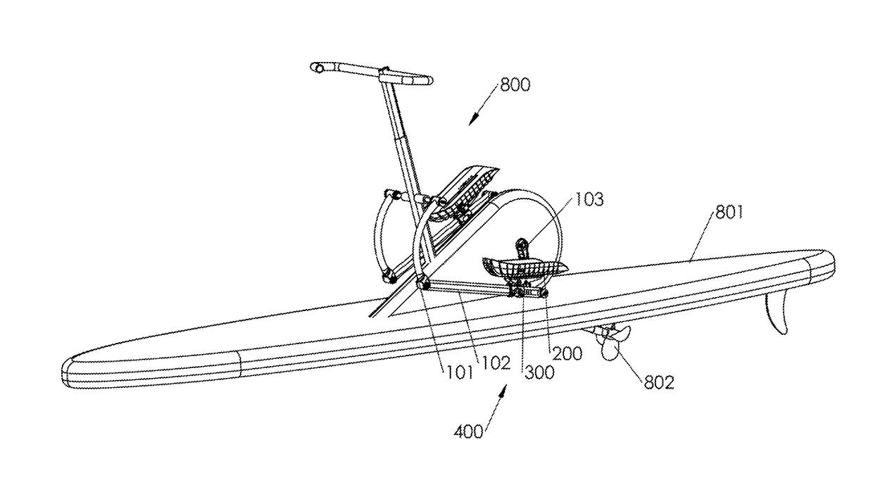
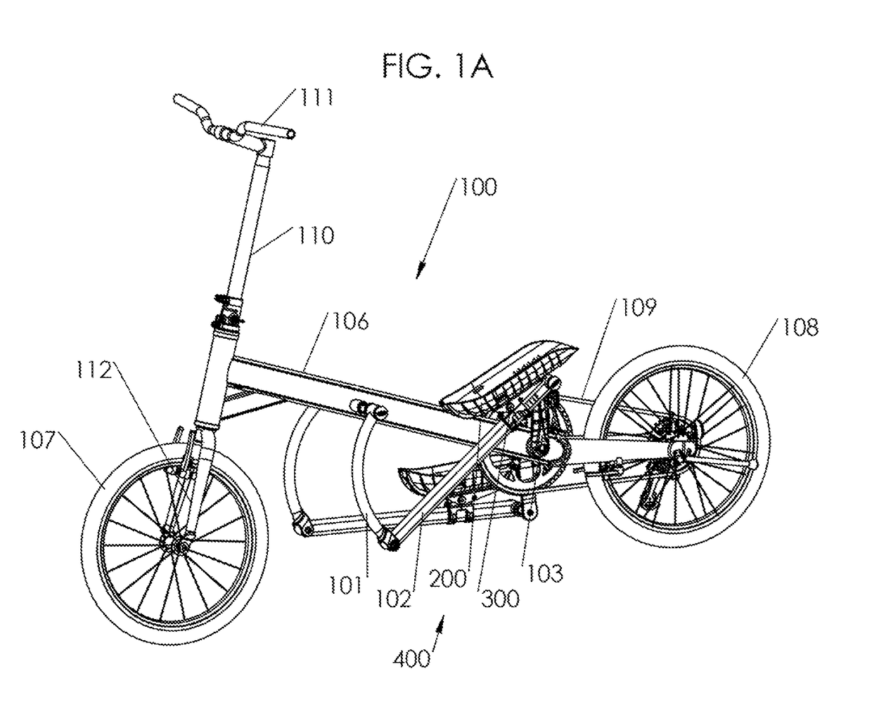
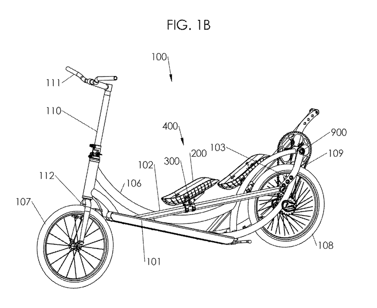
[0055]With reference to FIG. 1A, an embodiment of a rear-drive elliptical cycle 100 with short drive arms and pivoting foot platforms is shown. Before describing the pivoting foot platforms, the elliptical cycle will first be described. In alternative embodiments, the pivoting foot platforms are applied to other types of elliptically-driven human powered vehicles including, without limitation, elliptical cycles with two, three, or four wheels; elliptical cycles with arm levers in place of the handlebars; and elliptically driven watercraft (FIG. 1D). In a further embodiment, the pivoting foot platforms are applied to a stationary elliptical exercise machine (FIG. 1C) for commercial use and / or home use.

[0056]The elliptical cycle 100 includes a drive mechanism 400 mounted on a frame 106 on which one or more wheels (front wheel 107, rear / drive wheel 108) are mounted. Generally, the drive mechanism 400 comprises either a slider crank mechanism or a rocker crank mechanism. A drive mechani...


PUM


Abstract

An apparatus including a frame; a drive wheel coupled to the frame; first and second foot links operably coupled to said drive wheel to transfer power to said drive wheel so as to propel the apparatus; and each of said first and second foot links including a pivoting foot platform for receiving an operator's foot, said pivoting foot platform pivotally coupled to one of said first and second foot links so as to allow angular travel of the pivoting foot platform, the apparatus including one or more features to limit the angular travel of said pivoting foot platform.

Description

CROSS REFERENCE TO RELATED APPLICATION[0001]This application claims the benefit of prior provisional patent application No. 62 / 263,981, filed Dec. 7, 2015, which is incorporated by reference herein.BACKGROUND[0002]Field of the Invention[0003]The present invention relates generally to elliptical cycles, and particularly to foot platforms of elliptical cycles and other elliptical apparatuses.[0004]Related Art[0005]An elliptical cycle operates by the user standing atop foot platforms and using his legs to stride forward and rearward in a generally elliptical or ovate path causing the rear wheel to rotate and propel the elliptical cycle. Many different versions of the elliptical cycle are known in the art, employing different mechanisms to transfer power from the user to the rear wheel. For example, in one version of an elliptical cycle, an elliptical or ovate path is created by a slider crank mechanism comprised of guide tracks, drive arms and crank arms where a rear end of each drive ...

Claims


Application Information

Patent Timeline
Patent Type & Authority Patents(United States)
IPC IPC(8): B63H16/20A63B22/00B62M1/36B62K3/00B63B35/73A63B22/16A63B22/06
CPCB63H16/20A63B22/0046A63B22/0664B62K3/002B62M1/36B63B35/73A63B22/16A63B2022/0688B62M3/08B63B34/50
Inventor TEAL, BRENT C.PATE, BRYAN L.
Owner PT MOTION WORKS INC
Why Eureka
Try Eureka