Vertical take-off and landing drag rudder

a drag rudder and vertical take-off technology, applied in the field of rotorcraft, can solve the problems of increasing the instability of the directional stability of the aircraft, the size of other vtol aircraft, and the inability to adapt to the size of the aircra

Active Publication Date: 2018-07-03
SIKORSKY AIRCRAFT CORP
View PDF34 Cites 4 Cited by
  • Summary
  • Abstract
  • Description
  • Claims
  • Application Information

AI Technical Summary

Benefits of technology

[0005]In addition to one or more of the features described above, or as an alternative, further embodiments could include a drag rudder assembly that produces a stabilizing force on the wing structure during higher speeds of the aircraft in tandem rotor flight.
[0022]Technical function of a wing drag rudder at one end of a wing structure for a VTOL tail-sitter aircraft is to provide directional stability at higher speeds during tandem rotor flight, to provide minimal performance impact during wing-borne flight, and minimal to no impact on the aircraft's overall footprint to operate in certain confined environments.

Problems solved by technology

As a result, the proprotor tail-sitter aircraft can be used in certain confined environments, such as in an urban area or on a flight deck of a ship, while other VTOL aircraft, due to their size, have limited applicability.
However, as flight speed in tandem mode increases, the directional stability of the aircraft becomes more unstable due to the lack of a conventional empennage.

Method used


Image

  • Vertical take-off and landing drag rudder
  • Vertical take-off and landing drag rudder
  • Vertical take-off and landing drag rudder

Examples


Embodiment Construction

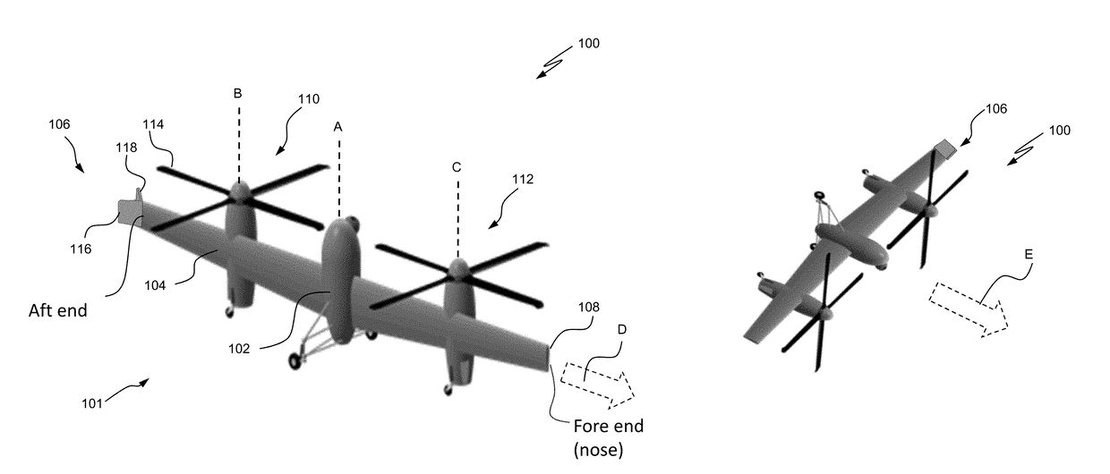
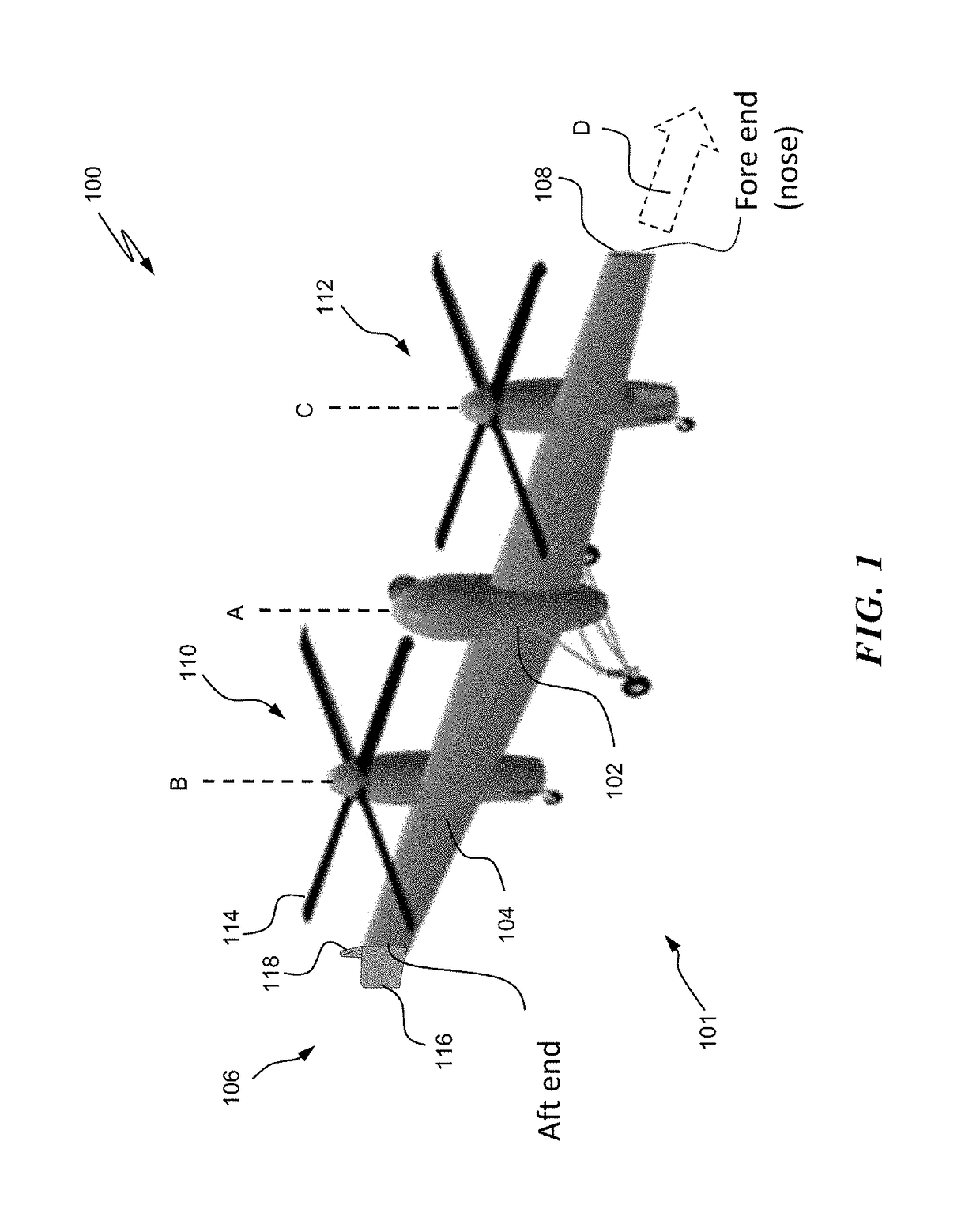
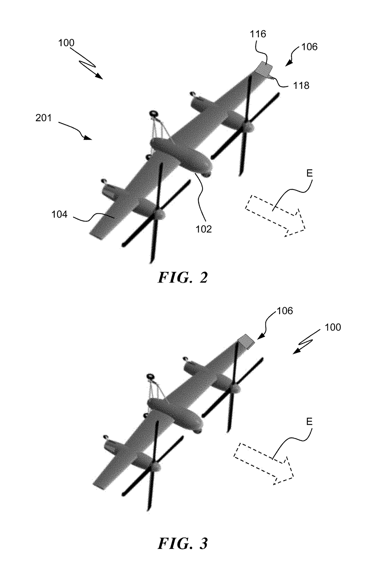
[0028]Referring now to the drawings, FIGS. 1-3 illustrate a perspective of an exemplary vertical take-off and landing (VTOL) vehicle in the form of a proprotor tail-sitter aircraft 100 according to an embodiment of the invention. As illustrated, tail-sitter aircraft 100 includes a fuselage 102, an elongated wing structure 104 attached to fuselage 102, and a drag rudder assembly 106 at one wingtip. Although a particular configuration of a proprotor tail-sitter aircraft 100 is illustrated and described in the disclosed embodiments, it will be appreciated that other VTOL tail-sitter configurations of aircraft that can operate in confined areas on land or on water including fixed-wing aircraft, tiltrotor aircraft, tiltwing aircraft, and other tail-sitting VTOL aircraft including micro air- or organic air-vehicles may also benefit from embodiments disclosed.

[0029]As illustrated in FIG. 1, an exemplary tail-sitter aircraft 100 is shown in tandem rotor flight mode 101 (i.e., rotor-borne fl...


PUM


Abstract

A system for a tail-sitter aircraft includes a fuselage having one or more propellers, a wing structure coupled to the fuselage, and a drag rudder assembly coupled to the wing structure, the drag rudder assembly including a first planar member that is coupled to a second planar member. The drag rudder assembly is configured to produce a stabilizing force on the wing structure during higher speeds of the aircraft in tandem rotor flight.

Description

CROSS-REFERENCE TO RELATED APPLICATIONS[0001]This application claims the benefit of U.S. provisional patent application Ser. No. 62 / 000,665, filed May 20, 2014, the entire contents of which are incorporated herein by reference.FIELD OF THE INVENTION[0002]The subject matter disclosed herein relates generally to the field of rotorcraft, and to a vertical take-off and landing tail-sitter aircraft with an asymmetric drag rudder at a wing tip for providing directional stability during hover flight.DESCRIPTION OF RELATED ART[0003]Typically, a vertical take-off and landing (VTOL) aircraft, e.g., a helicopter, tiltrotor, tiltwing, or a tail-sitter aircraft, can be airborne from a relatively confined space. Tail-sitter aircraft have a fuselage that is vertically disposed during take-off and hover and which transitions from a vertical flight state (i.e., rotor borne) to a horizontal flight-state (i.e., wing borne). In an example, some tail-sitter aircraft do not have a conventional empennage....

Claims


Application Information

Patent Timeline
Patent Type & Authority Patents(United States)
IPC IPC(8): B64C27/22B64C29/02B64C9/00B64C5/08
CPCB64C29/02B64C9/00B64C5/08
Inventor SCOTT, MARK W.CHEREPINSKY, IGOR
Owner SIKORSKY AIRCRAFT CORP
Why Eureka
Try Eureka