
System for sliding a door

a technology for sliding doors and sliding doors, applied in the direction of door/window accessories, wing operation mechanisms, wing accessories, etc., can solve the problems of increasing the force required to move the door by sliding, affecting the grip of the door, and disadvantages of manual operation of sliding doors

Inactive Publication Date: 2018-07-03
ETAB SOGAL FAB
View PDF16 Cites 0 Cited by
  • Summary
  • Abstract
  • Description
  • Claims
  • Application Information

AI Technical Summary

Benefits of technology

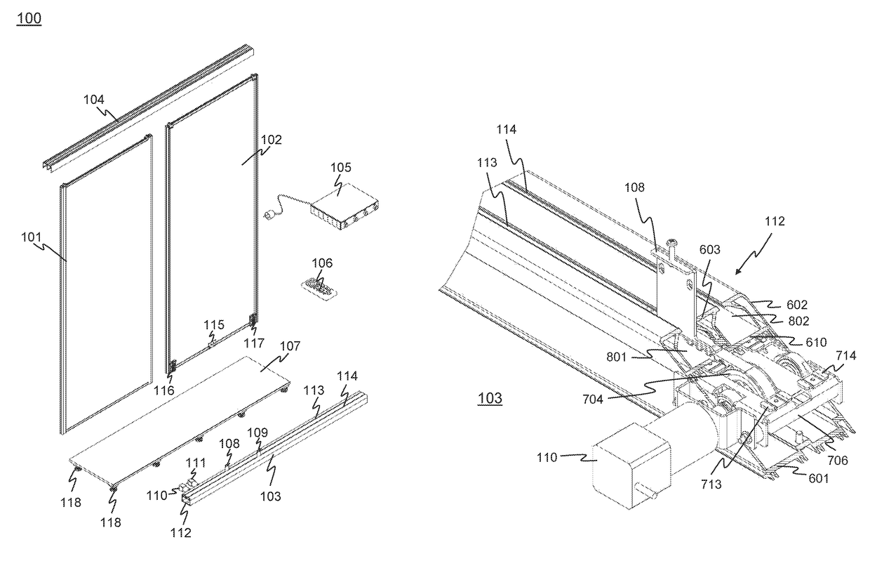
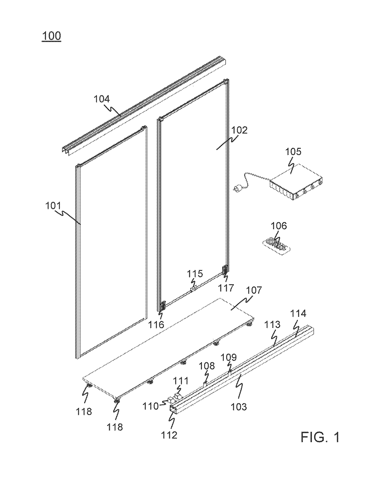
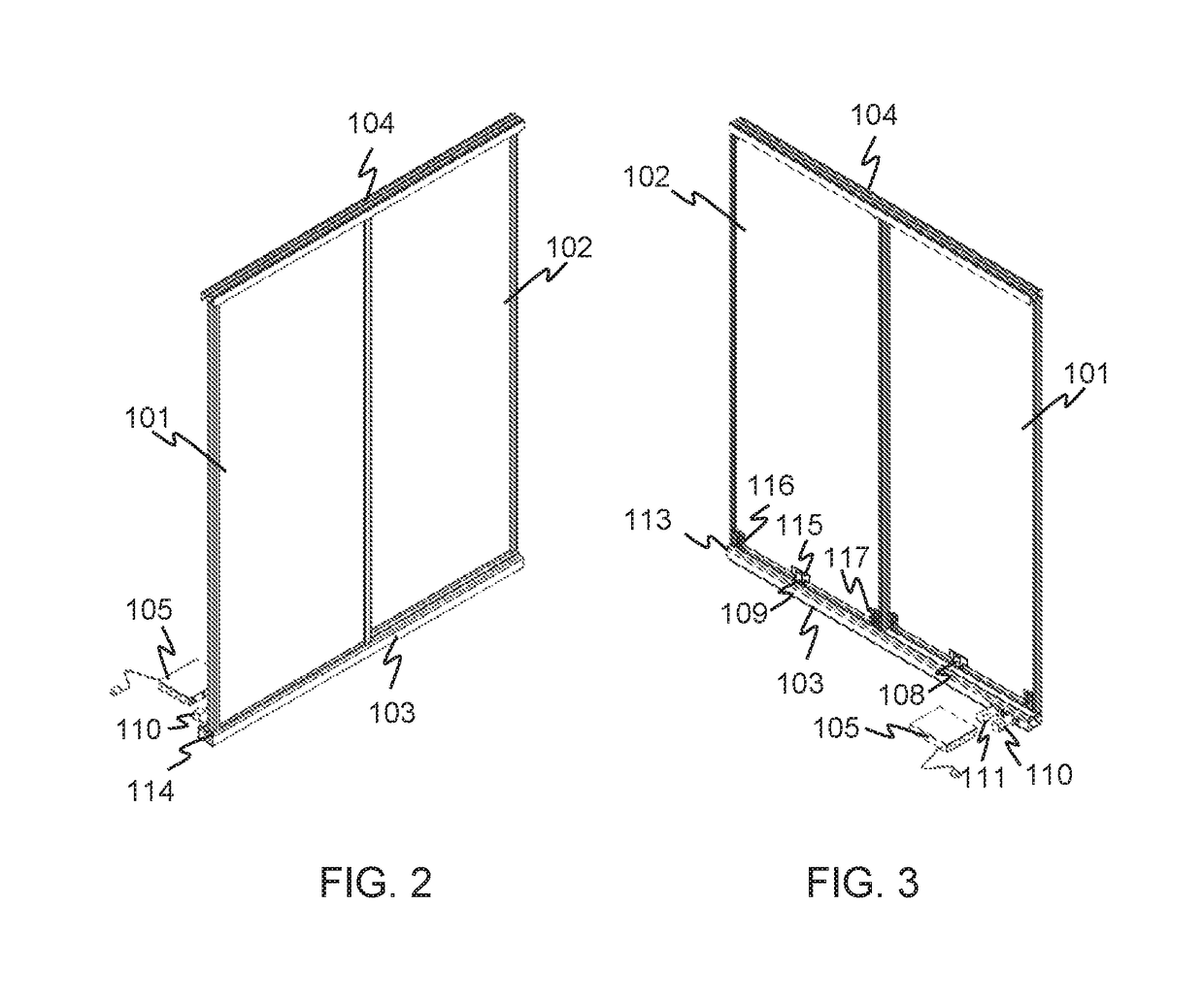
This patent describes a door system that can be easily installed and removed. The system includes a bottom slide rail that is heavy and supports multiple doors. The bottom rail can be easily attached to a wall using a simple attachment mechanism. The system also includes a top slide rail that can be attached to a flexible wall, such as a false ceiling. The system is compatible with existing doors and can be installed at relatively low costs. The system is safe, easy to use, and aesthetically pleasing. It is particularly suitable for making cupboards as the bottom slide rail is flush with the floor and provides safety against possible shear contacts. The system can be installed and removed quickly and easily. Overall, this is a high-quality, efficient, and safe door system that offers flexibility and safety in its installation.

Problems solved by technology

However, manual operation of a sliding door has disadvantages.
However, this type of damper system may introduce an additional resistance, which increases the force required to move a door by sliding.
Furthermore, for typically aesthetic reasons, a door may have a design which makes the door difficult to grip.
This introduces a difficulty to exert the force required to slide the door.
People with reduced physical capacities, such as the disabled, the elderly, or children, will find it difficult to move a door by sliding, for example to access a storage space.
These people may even be unable to move the door.
Whatever the case, manual operation of a sliding door may be a source of discomfort.
In addition, manual operation of a sliding door typically requires at least one free hand.
This is also a factor of discomfort and fatigue.
In addition, manual operation of a door creates a risk of injury.
There is also a risk of shearing feet at the bottom.
Fingers may be caught and sheared when front and rear doors cross each other.
Manual operation of a sliding door may also affect the aesthetics of the door.

Method used


Image

  • System for sliding a door
  • System for sliding a door
  • System for sliding a door

Examples


Embodiment Construction

[0013]There is a need for a solution to install relatively easily a system for sliding a door, in numerous different applications.

[0014]In this respect, the following points were taken into consideration. A system comprising a motorized top slide rail, for sliding a door in an automated manner, can be difficult to install. A motorized top slide rail is generally heavy. Consequently, this type of rail must be attached to a relatively rigid wall. However, a storage space to which the system is applied can be defined at the top by a wall which is relatively flexible, typically a false ceiling. In this type of embodiment, it will be necessary to provide relatively complex attachments, which pass through the false ceiling, to attach the top slide rail to a rigid wall, a “real” ceiling, located behind the false ceiling.

[0015]In addition, an environment in which a system for sliding a door is applied generally has geometrical and dimensional imperfections. This type of environment typicall...


PUM


Abstract

A system for sliding a door of, for example, a cupboard, includes a bottom slide rail suitable for being set on a surface such that the door can come to bear on the bottom slide rail. A connecting device slides in the bottom slide rail. This connecting device is secured to a bottom of the door. A drive device exerts a drive force on the connecting device to cause the connecting device to slide in the bottom slide rail.

Description

CROSS-REFERENCE TO RELATED APPLICATIONS[0001]This is a National Stage Entry into the United States Patent and Trademark Office from International PCT Patent Application No. PCT / FR2014 / 052127, having an international filing date of Aug. 26, 2014, which claims priority to French Patent Application No. 1358219, filed Aug. 27, 2013, the entire contents of both of which are incorporated herein by reference.TECHNICAL FIELD[0002]One aspect of the invention relates to a system for sliding a door in an automated manner. The door can be, for example, a cupboard door. One embodiment of the system can slide several doors along several parallel sliding axes. Another aspect of the invention relates to a cupboard.PRIOR ART[0003]A cupboard may comprise one or more doors which move by sliding. The doors are typically held between a bottom slide rail and a top slide rail. These slide rails comprise one or more slide tracks opposite each other. A slide track can accommodate one or more mechanisms with...

Claims


Application Information

Patent Timeline
Patent Type & Authority Patents(United States)
IPC IPC(8): E05D15/08E05F15/643E05D15/06
CPCE05D15/08E05F15/643E05D15/0686E05Y2900/20
Inventor ANGEBAULT, JOELDILE, LAURENT
Owner ETAB SOGAL FAB
Learn More