Unlock instant, AI-driven research and patent intelligence for your innovation.

Fuel cell system

a fuel cell and system technology, applied in the field of fuel cell systems, can solve the problems of deteriorating fuel cell performance, deteriorating reforming performance, and normal temperature desulfurizer cannot meet both of these requirements

Active Publication Date: 2018-07-03
PANASONIC CORP +1
View PDF12 Cites 1 Cited by
  • Summary
  • Abstract
  • Description
  • Claims
  • Application Information

AI Technical Summary

Benefits of technology

The fuel cell system described in this patent is designed to better handle problems that arise when starting to recycle gas after the hydro-desulfurizer has warmed up. Its design provides a more optimal solution to these issues than existing systems.

Problems solved by technology

When the raw material containing the sulfur component is supplied to an anode of the fuel cell through the reformer and the like, the anode is poisoned by the sulfur component, and this deteriorates a performance of the fuel cell.
Further, a reforming catalyst contained in the reformer is poisoned, and this deteriorates a reforming performance.
However, the normal temperature desulfurizer cannot satisfy both of these requirements.

Method used


Image

  • Fuel cell system
  • Fuel cell system
  • Fuel cell system

Examples


embodiment 1

[0029]The present inventors have diligently studied problems caused when starting supplying a recycled gas to a recycle passage after warm-up of a hydro-desulfurizer is completed. As a result, the present inventors have obtained the following findings.

[0030]A fuel cell system may adopt a method in which: when the warm-up of the hydro-desulfurizer is slower than the warm-up of a reformer and a fuel cell, the fuel cell starts generating electric power before the completion of the warm-up of the hydro-desulfurizer; and after the completion of the warm-up of the hydro-desulfurizer, a flow route of the raw material is switched from a route through which the raw material flows to the normal temperature desulfurizer to a route through which the raw material bypasses the normal temperature desulfurizer and flows to the hydro-desulfurizer. Further, the fuel cell system may adopt another method in which after the completion of the warm-up of the hydro-desulfurizer, the above switching of the ...

embodiment 2

[0055]The fuel cell system of Embodiment 2 is configured such that the fuel cell system of Embodiment 1 includes: a vaporizer operative to vaporize water supplied to the reformer; and a water supplier operative to supply the water to the vaporizer, wherein: the reformer generates the reformed gas using steam and the raw material; when the temperature of the hydro-desulfurizer reaches the predetermined temperature, the controller increases a flow rate of the water from a predetermined flow rate by a flow rate corresponding to the flow rate of the recycled gas, and then, the controller starts supplying the recycled gas to the recycle passage; and after the recycled gas reaches the upstream end of the recycle passage through the raw material supply passage, the controller returns the flow rate of the water to the predetermined flow rate.

[0056]While the fuel cell is generating the electric power, the predetermined flow rate is a flow rate corresponding to a predetermined electric power ...

example 1

Device Configuration

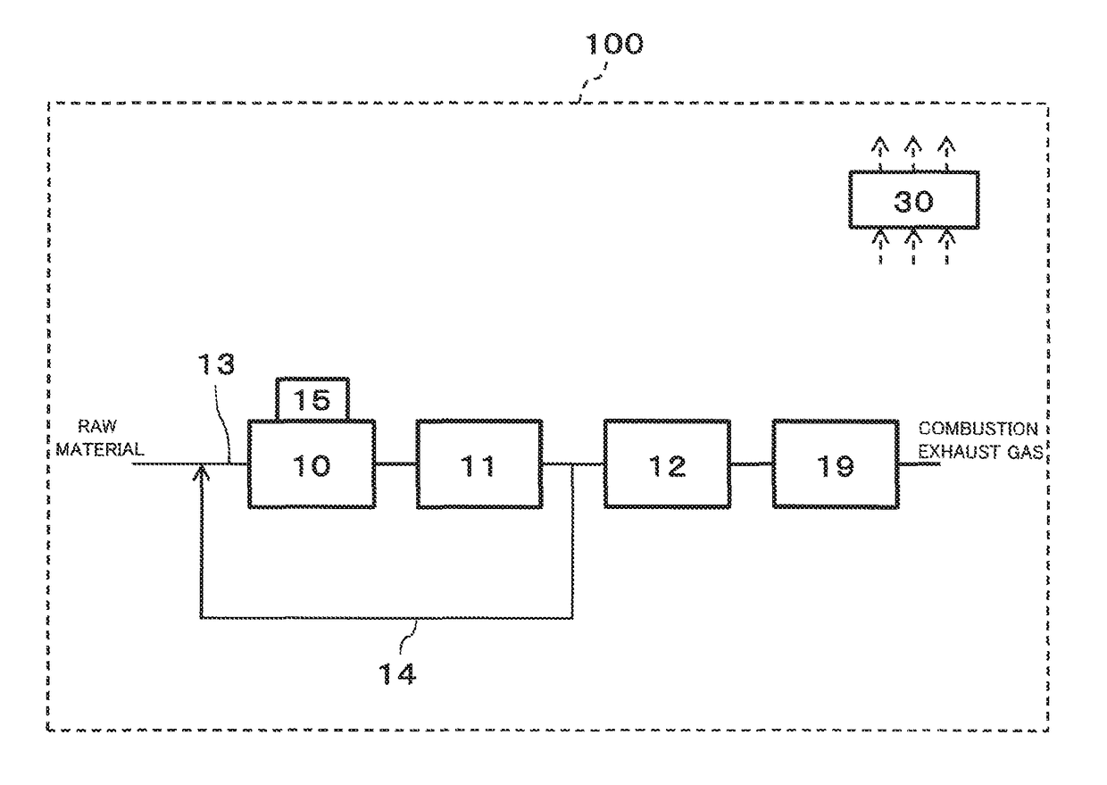
[0070]The fuel cell system 100 of Example 1 is the same in configuration as the fuel cell system 100 shown in FIG. 1 or 2. Since Example 1 is the same in configuration as Embodiment 1 or 2, an explanation of the configuration thereof is omitted.

[0071]Operations

[0072]FIG. 3 is a flow chart showing one example of operations of the fuel cell system of Example 1 of Embodiment 2. The following operations are performed by the control program of the controller 30.

[0073]Example 1 explains an example in which the supply of the recycled gas to the recycle passage 14 is started in a case where the warm-up of the hydro-desulfurizer 10 is faster than the warm-up of the reformer 11 and the warm-up of the fuel cell 12, for example, while the fuel cell system 100 is starting up and before the electric power generation of the fuel cell 12 is started.

[0074]First, whether or not the temperature of the hydro-desulfurizer 10 is not less than the predetermined temperature is determine...


PUM

PropertyMeasurementUnit
temperatureaaaaaaaaaa

Abstract

A fuel cell system includes: a reformer generating a reformed gas using a raw material; a fuel cell generating electric power; a raw material supply passage; a hydro-desulfurizer operative to remove sulfur component in the raw material; a recycle passage through which the reformed gas is supplied to the raw material supply passage provided upstream of the hydro-desulfurizer; a temperature detector detecting a temperature of the hydro-desulfurizer; and a controller, wherein: when the temperature of the hydro-desulfurizer reaches a predetermined temperature, the controller increases a flow rate of the raw material from a predetermined flow rate by a flow rate corresponding to a flow rate of the recycled gas, and then, the controller starts supplying the recycled gas to the recycle passage; and after the recycled gas reaches an upstream end of the recycle passage, the controller returns the flow rate of the raw material to the predetermined flow rate.

Description

RELATED APPLICATIONS[0001]This application is the U.S. National Phase under 35 U.S.C. § 371 of International Patent Application No. PCT / JP2015 / 000683, filed on Feb. 13, 2015, which in turn claims the benefit of Japanese Application No. 2014-028742, filed on Feb. 18, 2014, the disclosures of which Applications are incorporated by reference herein.TECHNICAL FIELD[0002]The present invention relates to a fuel cell system.BACKGROUND ART[0003]In recent years, fuel cell systems have been developed and commercialized as distributed power generation systems. An organic compound containing carbon and hydrogen is supplied as a raw material to the fuel cell system. In the fuel cell system, for example, a fuel cell reforms therein the raw material to generate a hydrogen-containing reformed gas, or a reformer provided outside the fuel cell reforms the raw material to generate the reformed gas. When the reformed gas is generated as above, the fuel cell can utilize hydrogen in the reformed gas and ...

Claims


Application Information

Patent Timeline
Patent Type & Authority Patents(United States)
IPC IPC(8): H01M8/04H01M8/0662H01M8/04225H01M8/04089C01B3/38H01M8/04746H01M8/04701H01M8/04537H01M8/04858H01M8/0432H01M8/0612
CPCH01M8/0618H01M8/04925H01M8/04373C01B3/382H01M8/04097H01M8/04225H01M8/04619H01M8/04738H01M8/04776H01M8/0675C01B2203/0244C01B2203/0495C01B2203/066C01B2203/067C01B2203/107C01B2203/1058C01B2203/1064C01B2203/127C01B2203/1217C01B2203/1235C01B2203/1241C01B2203/1247C01B2203/1252C01B2203/1288C01B2203/148C01B2203/84Y02E60/50
Inventor ONUMA, SHIGENORITANIGUCHI, NOBORUKANEKO, YASUSHISUKAWA, TORUSAKAI, OSAMUMIKAMI, YUICHISHIRAHAMA, HIROSHIOTSUKA, TOSHIHARU
Owner PANASONIC CORP