
Exercise machine and method for use in a supine position

a supine position and exercise machine technology, applied in the field of exercise machines or apparatus and methods, can solve the problems of affecting health, affecting the recovery time after healing, and significant muscle strength loss, and achieve the effect of resisting rocking or wobbling of the apparatus

Active Publication Date: 2018-07-10
U S GOVERNMENT REPRESENTED BY THE DEPT OF VETERANS AFFAIRS +1
View PDF21 Cites 16 Cited by
  • Summary
  • Abstract
  • Description
  • Claims
  • Application Information

AI Technical Summary

Benefits of technology

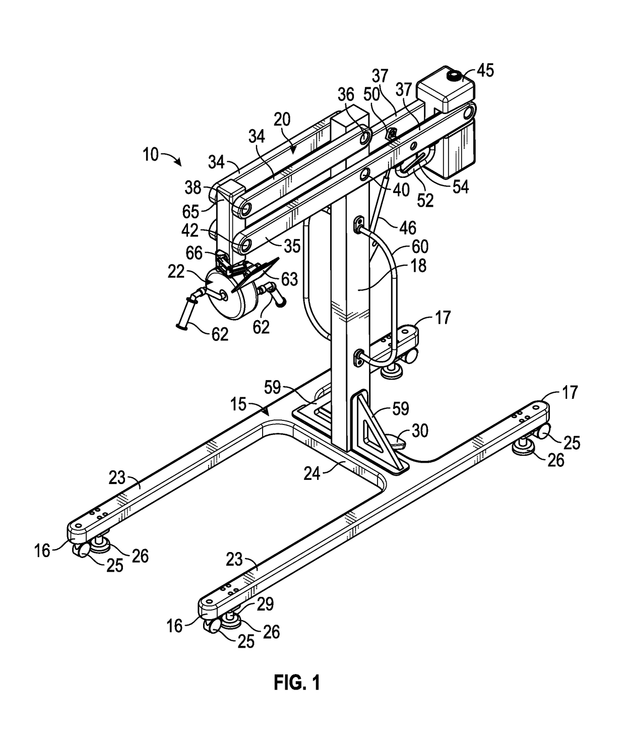
[0010]In one aspect, the anchoring system is configured to raise some or all of the wheels off the floor to provide a stable base during performance of exercise. In one aspect, the anchoring system comprises plurality of expandable feet on the mobile base which are movable between a raised, inoperative position and a lowered, ground-engaging or operative position in which the caster wheels are raised from the ground. In an alternative aspect, the anchoring system comprises remotely activated wheel locks associated with the caster wheels, providing mobility to the base when unlocked and providing stability to the base when locked, without the need to lift the caster wheels from the ground. Both alternatives provide a stable base during performance of exercise. In one aspect, the expandable feet or remotely lockable casters may be actuated to move back and forth between the inoperative and operative positions by a foot pedal, hand lever or other manually operable device.
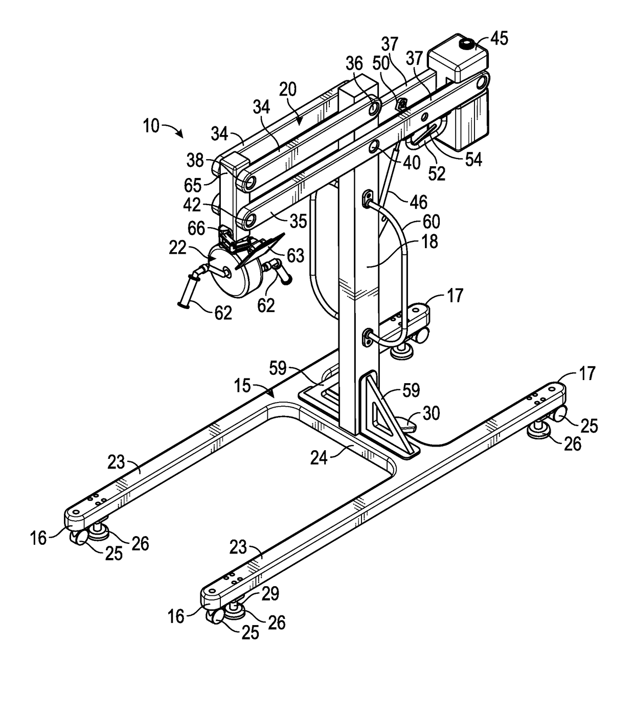
[0014]The mobile base of the exercise machine or apparatus allows an exercise device to be moved freely between patients or other individuals lying supine in bed while the anchoring system is in an inoperative position, and easily slides partially under a bed until the upright support is adjacent the side of the bed with the exercise device suspended at a selected exercise position over the bed for access by the patient. Once in the proper position for use by the patient, the base can be locked in place by deployment of the anchoring system with caster wheels raised from the ground, providing a stable platform or base which is capable of handling complex movements and loading associated with exercise machines, resisting rocking or wobbling of the apparatus while a patient is performing exercise.

Problems solved by technology

However, prolonged bed rest can lead to significant loss of muscle strength, and can negatively affect health in other ways as well as lengthening recovery time after healing.
However, most exercise machines are not suitable for use by a person in a supine position.
As an example, many arm ergometers (also known as UBE or upper body ergometers) are currently available on the market, but none are able to be used by a person lying in a supine position in a hospital bed.
Such an exercise is not appropriate for patients with spinal cord injury or other patients bedridden for extended periods of time, due to shear on the tissues of the back, buttocks and legs, placing patients at greater risk of developing pressure ulcers.
The mounting fixture would also be difficult to mount on different types of hospital beds due to variation in hospital bed sizes and foot end structures, and demounting and remounting was required to move the device from patient to patient.
Both of these devices are only designed for lower limb pedaling exercise when a user is in a supine position, and are not designed for upper limb exercise while supine in a hospital bed.
Prior exercise machines for use when lying supine in a bed have disadvantages such as instability during exercise because of the mounting or support arrangement, and difficulty in moving the machines from one bed to another.

Method used


Image

  • Exercise machine and method for use in a supine position
  • Exercise machine and method for use in a supine position
  • Exercise machine and method for use in a supine position

Examples


Embodiment Construction

[0026]Certain embodiments disclosed herein provide for an exercise machine or apparatus configured for allowing patients or exercisers lying in a supine position in a bed to perform exercises. In one embodiment, the apparatus includes a stable base which has caster wheels for transporting the apparatus to a desired position at a bed and an anchoring system to raise the caster wheels from the ground when the desired position is reached so that stability is maintained and wobbling during exercise performance is reduced or eliminated.

[0027]After reading this description it will become apparent to one skilled in the art how to implement the invention in various alternative embodiments and alternative applications. However, although various embodiments of the present invention will be described herein, it is understood that these embodiments are presented by way of example only, and not limitation. As such, this detailed description of various alternative embodiments should not be constr...


PUM


Abstract

An exercise machine has a mobile base and an upright support extending upwards from the mobile base. An upper support assembly extends forward from an upper portion of the upright support and an exercise device is suspended from the upper support assembly at a location spaced forward from the upright support. The mobile base has caster wheels and can be positioned from either side of a bed so as to extend partially under a bed with the upright support located on one side of the bed and the exercise device suspended over the bed in a position accessible by a patient lying supine in the bed for performing exercise. An anchoring system resists movement of the base for stability when exercise is performed.

Description

BACKGROUND[0001]Field of the Invention[0002]The present invention relates generally to exercise machines or apparatus and methods for use by persons who are in a supine position in bed, for example patients on bed rest or others who prefer exercising in this position for safety, more comfort, pain relief or the like.[0003]Related Art[0004]Exercise is widely accepted as an important element in maintaining health and wellness. Many exercise machines exist to provide users with a variety of movements, such as treadmills, stationary cycles, arm ergometers, weight lifting machines, and the like. Most exercise machines are used in ways that create complex movements and loading to the machines. For this reason, exercise machines are typically mounted on stable structural bases that stand on the floor and are immobile. In addition, most exercise machines are designed for exercise in a standing or seated position and generally remain in a room or gym that a user must go to for exercise.[0005...

Claims


Application Information

Patent Timeline
Patent Type & Authority Patents(United States)
IPC IPC(8): A63B22/00F16M11/42A63B71/00A63B22/06A63B71/02F16M11/24B60B33/00F16M11/18A63B21/062A63B21/00A63B23/12A63B23/04A63B23/035A63B21/22A63B21/16A63B21/055A63B21/008A63B71/06A63B21/005
CPCF16M11/42A63B22/0005A63B22/0046A63B22/0605A63B22/0694A63B71/0054A63B71/023B60B33/0089B60B33/0092B60B33/0094F16M11/18F16M11/24A63B22/0002A63B2225/093A63B21/005A63B21/0058A63B21/00061A63B21/00069A63B21/0083A63B21/0087A63B21/0552A63B21/0628A63B21/16A63B21/225A63B22/0007A63B22/0076A63B23/03525A63B23/0405A63B23/1209A63B71/0009A63B71/0622A63B2022/0623A63B2071/025A63B2208/0252A63B2210/04A63B2225/09A61H1/0214A61H1/0274A61H2201/0142A61H2201/0157A61H2201/1215A61H2201/1635A61H2203/0406A61H2203/0456A63B2071/0658A63B2208/0204A63B2208/0233
Inventor GOLDISH, GARYHANSEN, ANDREWNICKEL, ERICFERGUSON, JOHN
Owner U S GOVERNMENT REPRESENTED BY THE DEPT OF VETERANS AFFAIRS
Learn More