Chest compression device

a compression device and chest technology, applied in the direction of heart defibrillators, supine patient support/support, heart stimulation, etc., can solve the problems of high quality manual compression, dangerous for medical personnel, and the inability to achieve clear improvement in patient survival with a devi

Active Publication Date: 2018-07-17
UNIV OSLO HF
View PDF26 Cites 3 Cited by
  • Summary
  • Abstract
  • Description
  • Claims
  • Application Information

AI Technical Summary

Benefits of technology

[0016]The support structure is preferably a rigid structu

Problems solved by technology

They can give consistent chest compressions, can free the personnel to accomplish other chores and can be used during transport where high quality manual compressions are impossible and are dangerous for the me

Method used


Image

  • Chest compression device
  • Chest compression device
  • Chest compression device

Examples


Embodiment Construction

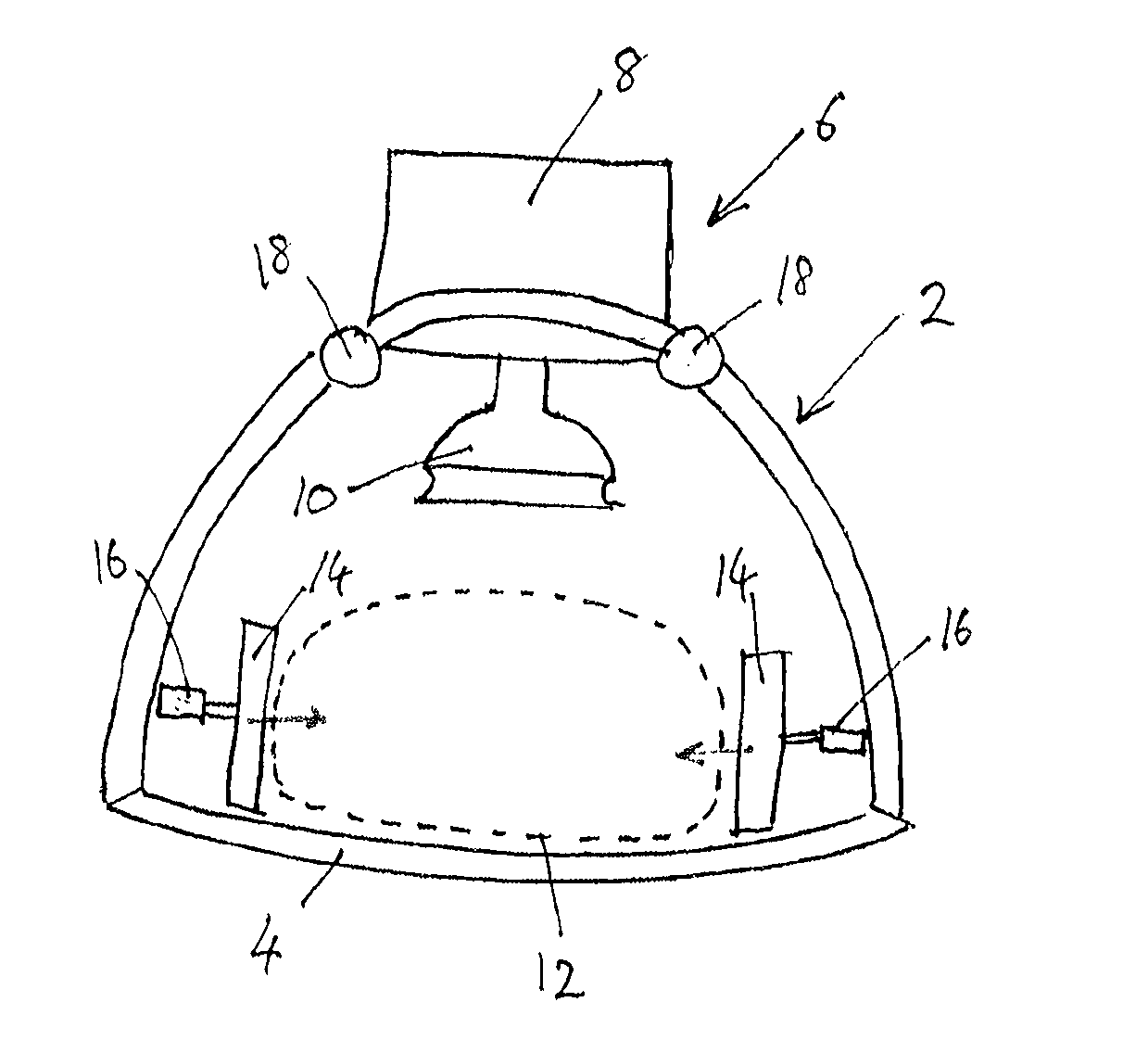
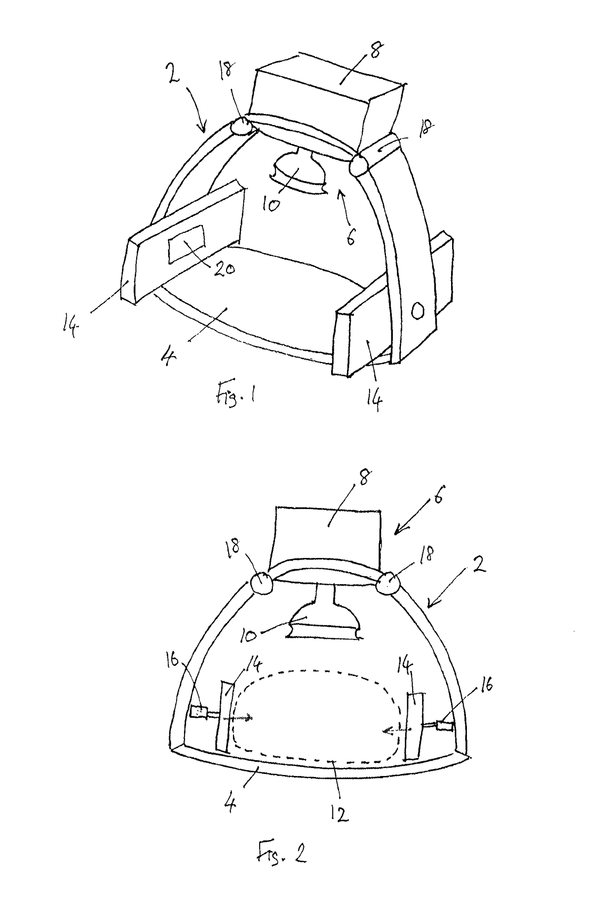
[0033]The main features of the chest compression device, including the piston arrangement for compressing the chest, can be similar to those found in known products such as the LUCAS™ Chest Compression System manufactured and developed by Joffe AB / Physio-Control of Sweden. Thus, as shown in FIGS. 1 and 2 one preferred embodiment of the device comprises a support structure in the form of an arch 2 over a back plate 4 and supporting a piston device 6, which is to be positioned over the patient's sternum. The patient hence lies on their back with the back plate 4 beneath them and the arch 2 holds the piston device 6 above the chest. The piston device 6 includes an actuator and controller 8 along with a piston 10 that is arranged to compress the chest when driven toward the chest by the actuator. FIG. 2 includes an indication of the positioning of the chest within the chest compression device and shows a schematic cross-section of the torso 12.

[0034]The device is further provided with l...


PUM


Abstract

A chest compression device for cardiopulmonary resuscitation may include a support structure for placement about a patient's chest and for holding a chest compressor above a patient's sternum; a chest compressor mounted on the support structure; and lateral chest supports attached to the support structure at points laterally on either side of the chest when the device is in use, such that the lateral chest supports will apply lateral pressure to the sides of the chest synchronised with a chest compression by the chest compressor.

Description

TECHNICAL FIELD[0001]The invention relates to a chest compression device for use in cardiopulmonary resuscitation (CPR) and to a method of chest compression in cardiopulmonary resuscitation.BACKGROUND OF THE INVENTION[0002]Sudden cardiac arrest (SCA) outside the hospital is a leading cause of death in the western world, and globally the incidence is estimated to 55 per 100 000 person-years. The number of patients surviving to hospital discharge remains low. A recent meta-analysis stated the aggregate survival rate to hospital discharge to be 7.6%, which has not significantly changed in almost 30 years.[0003]Chest compression during cardiopulmonary resuscitation (CPR) remains one of few proven treatments for patients suffering from sudden cardiac arrest, supplying blood to the critical organs—brain and heart-muscle—until spontaneous circulation hopefully resumes. It has been shown that a higher quality of CPR improves the outcome. In both experimental and clinical studies chest compr...

Claims


Application Information

Patent Timeline
IPC IPC(8): A61H31/00A61H9/00A61N1/39
CPCA61H31/007A61H9/0078A61H31/006A61H31/008A61H2031/002A61N1/39A61H2201/0214A61H2201/0242A61H2201/0278A61H2201/10A61H2031/003A61N1/39044
Inventor WIK, LARSERIKSEN, MORTENJOHANSEN, JO KRAMERSTEEN, PETTER ANDREASSUNDE, KJETIL
Owner UNIV OSLO HF
Why Eureka
Try Eureka