Projection mapping system and apparatus

a projection mapping and projection system technology, applied in the direction of projection devices, instruments, picture reproducers using reradiation, etc., can solve the problems of large volume, difficult use, and relatively few advancements of hand tools

Active Publication Date: 2018-07-17
NEWTONOID TECH L L C
View PDF2 Cites 5 Cited by
  • Summary
  • Abstract
  • Description
  • Claims
  • Application Information

AI Technical Summary

Benefits of technology

[0004]The following presents a simplified summary of the invention in order to provide a basic understanding of some aspects of the invention. This summary is not an extensive overview of the invention. It is not intended to identify critical elements of the invention or to delineate the scope of the invention. Its sole purpose is to present some concepts of the invention in a simplified form as a prelude to the more detailed description that is presented elsewhere herein.
[0005]In one embodiment, a projection system includes a projection apparatus embodied in a housing secured to a user. The projection apparatus has a processor in data communication with a networking device, at least one input/output device, and computer memory. The computer memory includes a program with machine readable instructions that, when effected by processor, perform the following steps: (a) determine an edge of a surface to be measured; (b) project an initial image onto the surface, the initial image being based on a predetermined set of conditions; (c) determine a substantially perpendicular distance D1 between the projection apparatus and the surface; (d) determine a distance D2 between the projection apparatus and the edge of the surface; (e) calibrate the initial image based on the distances D1 and D2 determined in steps (c) and (d); and (f) project an updated image onto the surface.
[0006]In another embodiment, a projection system comprises a reference device comprising a processor in data communication with a networking device and at least one input/output device. The reference device is placed at an edge of a surface to be measured. The system further includes a projection apparatus embodied in a housing secured to a user. The projection apparatus compr

Problems solved by technology

Generally speaking, hand tools have seen relatively few advancements over the years.
However, they tend to be bulky and somewhat difficult to use, as a user must both lay out the tape measure upon a surface and mark the surface wh

Method used


Image

  • Projection mapping system and apparatus
  • Projection mapping system and apparatus
  • Projection mapping system and apparatus

Examples


Embodiment Construction

[0019]Currently, the majority of hand tools do not incorporate any type of projection system. One exception is distance finders which use ultrasonic and / or laser reflection techniques to determine a distance from the user to a surface. The user points the tool at a surface, presses a button to activate the laser, and the tool measures the distance to the location where the laser is pointed. While these devices are useful for determining the distance to a point, they are not tape measures. A tape measure cannot be substituted for a laser pointer where the user desires to, for example, mark a surface for cutting.

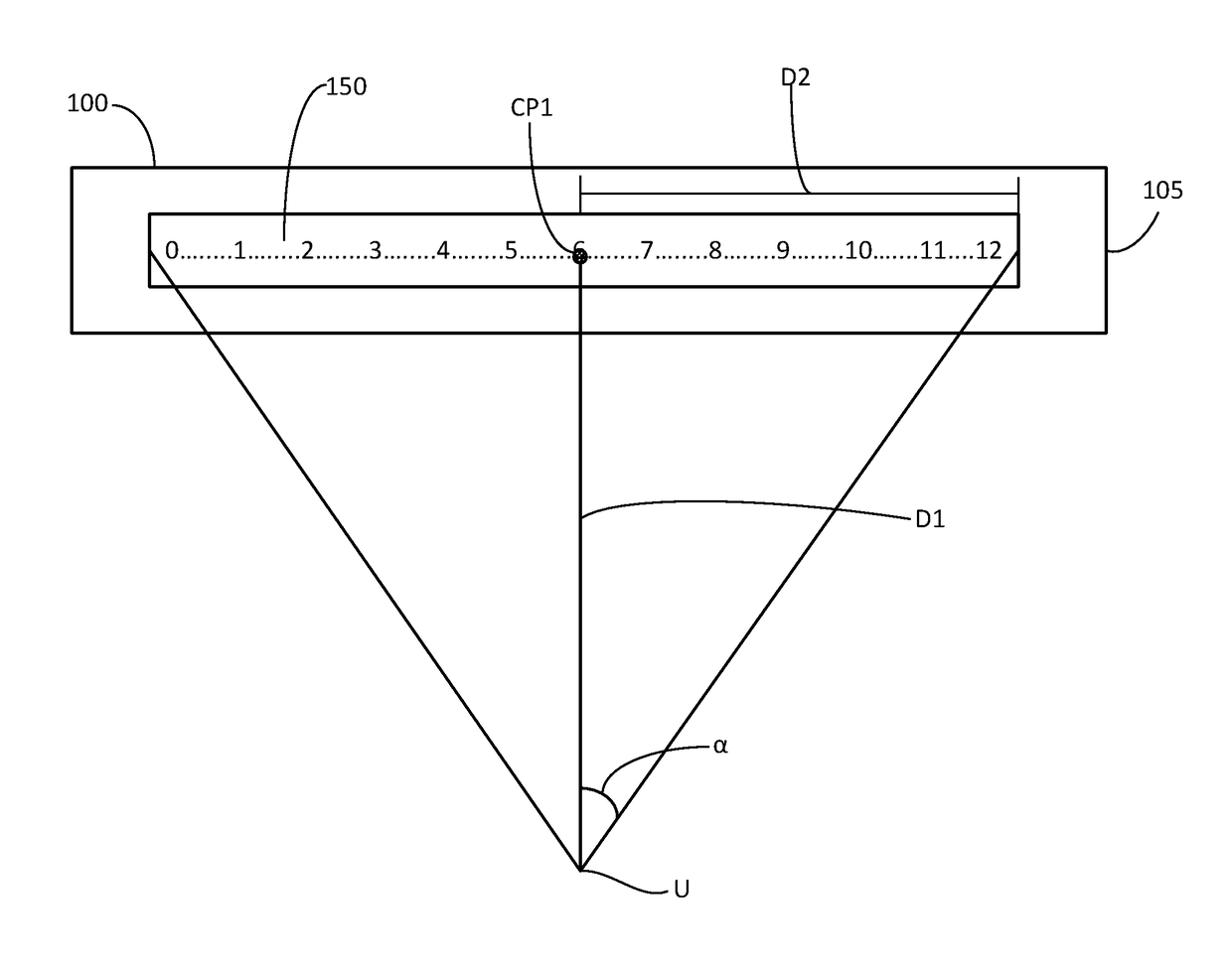
[0020]Disclosed herein are embodiments of projection mapping apparatus which may be useful as a tape measure projection device. Those of skill in the art shall understand that while reference is made herein to apparatus that project tape measures, other projection apparatus are contemplated within the scope of the invention and will become apparent from the description provide...


PUM


Abstract

A projection system includes a projection apparatus embodied in a housing secured to a user. The projection apparatus has a processor in data communication with a networking device, at least one input/output device, and computer memory. The computer memory includes a program with machine readable instructions that, when effected by processor, perform the following steps: (a) determine an edge of a surface to be measured; (b) project an initial image onto the surface, the initial image being based on a predetermined set of conditions; (c) determine a substantially perpendicular distance D1 between the projection apparatus and the surface; (d) determine a distance D2 between the projection apparatus and the edge of the surface; (e) calibrate the initial image based on the distances D1 and D2 determined in steps (c) and (d); and (f) project an updated image onto the surface.

Description

FIELD OF INVENTION[0001]The invention relates to projection mapping apparatus. More specifically, the invention relates to an apparatus for projecting a tape measure onto a surface.BACKGROUND[0002]Projection displays have been around for several years in many different forms. While many industries take advantage of projection technology, one industry where such technology has been largely ignored is hand tools. Generally speaking, hand tools have seen relatively few advancements over the years. This is especially true when it comes to tape measures.[0003]Currently, tape measures are effective for their intended purpose. However, they tend to be bulky and somewhat difficult to use, as a user must both lay out the tape measure upon a surface and mark the surface while attempting to hold the tape measure in position. This often results in frustration, especially when the tape measure becomes dislodged from its desired position, twists, or the user has to take measure many different sur...

Claims


Application Information

Patent Timeline
IPC IPC(8): G03B21/14G06F17/30G01S17/08H04N9/31
CPCH04N9/3185H04N9/3173G01S17/08G06F17/30247G03B21/147G01B3/10H04N9/3194G01S17/46G06F16/583G01B11/02H04N9/3141H04N9/3188
Inventor STATON, FIELDING B.STRUMPF, DAVID
Owner NEWTONOID TECH L L C
Why Eureka
Try Eureka