On board unit with power management

a technology of power management and on-board units, applied in traffic control systems, liquid/fluent solid measurement, instruments, etc., can solve the problems of reducing the time the obu can be used, consuming a lot of power idling, and reducing the battery power, so as to save power and reduce the time , the effect of fast transition

Active Publication Date: 2018-07-24
KAPSCH TRAFFICCOM AB
View PDF9 Cites 1 Cited by
  • Summary
  • Abstract
  • Description
  • Claims
  • Application Information

AI Technical Summary

Benefits of technology

[0017]Today some applications require that the OBU is tracked through the communication zone in order to trigger location dependent events like opening of a barrier or having the OBU beeping at an exact location. Other installations require synchronization between the OBU position and other sensors such as a camera or ground loops. The tracking of an OBU within the communication zone for these installations results in an active time of the OBU that might be considerably longer than expected, and in some cases, e.g. during queues or common stop and go traffic, this drastically reduces the battery life time of the OBU.
[0018]As described the present subject matter reduces the active time of the OBU within the communication zone considerably, by setting the OBU in a tracking mode of operation where it is only required to be active for a very short time interval transmitting tracking frames that the RSU can use for localization of the OBU within said communication zone at a predefined repetition period.
[0020]The OBU may need to boot up to be set into said active mode from said sleep mode. The OBU may receive a wake up command from the RSU when the vehicle approaches or enters the communication zone. During boot up the OBU loads all the necessary software and starts the necessary hardware. If the OBU enters the communication zone but is not in a position where the transaction shall take place, the OBU, if requested so by the RSU, enters the tracking mode by shutting down at least the communication unit. This means that the OBU is still booted up but has entered a power saving mode. The fact that the OBU is booted up means that less time is needed for the OBU to make a transition from the tracking mode to active mode than from the sleep mode to active mode. This enables the function of the OBU to be ready for a transaction while saving power compared to being in a continuous active mode.
[0021]At least one register may be kept in a memory of the OBU enabling the OBU to being set into said tracking mode without having to boot up.
[0022]As stated above the OBU does not need to boot up when the OBU makes a transition from the tracking mode to the active mode. During the boot up the OBU is setup for being able to communicate with another device, and in the initialisation phase of the transaction, RSU unique information needed for subsequent communication are transferred to the OBU. This information may be stored in the OBU's memory when entering the tracking mode. Other relevant data and register information loaded during boot up may also be stored in the OBU's memory. Having this information available in the OBU enables a very fast transition between tracking mode and active mode.
[0030]The OBU is provided with a power management scheme, i.e. it is a device that utilizes a power saving mode and activates when excited with a certain pattern from the RSU. By providing an OBU according to the above it is possible to realize a transaction where the OBU uses less power during the tracking mode than if it were active throughout the communication zone. By incorporating a data storage the necessary functions and information that has to be loaded after boot-up of the OBU and initialisation of the communication link can be stored in the data storage. Appropriate low power data storage can be accessed swiftly when the functions and / or information are required when the OBU make a transition from tracking mode to active mode.

Problems solved by technology

This inherently means that the OBU consumes a lot of power idling while waiting for a command from the RSU to send such a tracking frame.
For an OBU that is battery powered this severely reduces the battery power and thereby reduces the time the OBU can be used before the battery is drained.

Method used


Image

  • On board unit with power management
  • On board unit with power management
  • On board unit with power management

Examples


Embodiment Construction

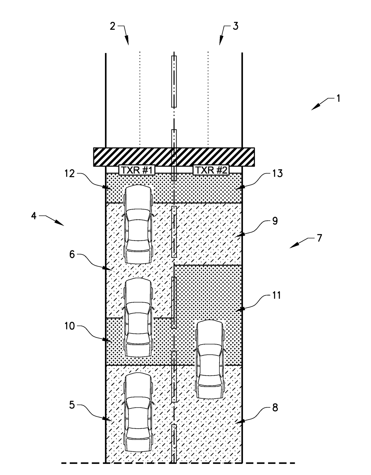
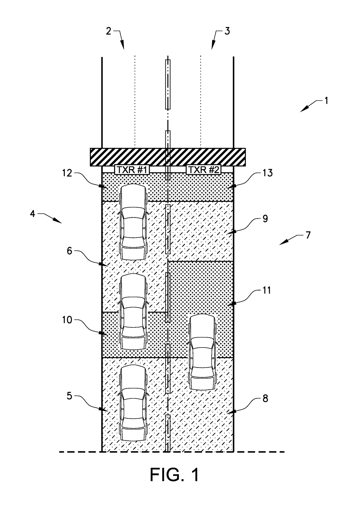
[0037]The protocol used for tolling is defined in IEEE 1609.11 and is based on a master-slave concept where the RSU is the master and the OBU is the slave. IEEE 1609.11 is part of the family of standards for Wireless Access in Vehicular Environments (WAVE). One of the basic features of the WAVE standard is that any two WAVE devices can setup an ad-hoc network exchanging information. This inherently means that a WAVE OBU utilizes a full WAVE transceiver and can transmit data itself without any interaction from the RSU.

[0038]FIG. 1 schematically shows an illustration of a tolling station 1 that has been set up such that the transaction shall begin at a first predetermined position, i.e. upon entering a transaction zone and be reported at a second predetermined position, i.e. upon entering a reporting zone. The tolling station 1 in FIG. 1 comprises a first lane 2 and a second lane 3. It is of course possible for the tolling station 1 to have more than two lanes. The tolling station 1 c...


PUM


Abstract

Described are an on board unit (OBU) and a method to control an OBU within a communication zone of a road side unit (RSU), said OBU can be set into an active mode and a sleep mode. Said OBU is set into sleep mode upon receiving a release command from said RSU, and the OBU electronics are shut down so no or a minimum of power is consumed, and is set into active mode when entering said communication zone. A communication unit of said OBU is thereby powered such that the OBU can communicate with said RSU. Said OBU can be set into a tracking mode by said RSU, whereby in said tracking mode at least said communication unit is shut down and a timer is activated in said OBU, such that said OBU can restart said communication unit within a specified time limit from when it is shut down.

Description

CROSS-REFERENCE TO RELATED APPLICATION(S)[0001]This application is a U.S. national phase of International Application No. PCT / EP2013 / 064075 filed on Jul. 3, 2013, which designated the U.S. and claims priority to European Patent Application No. 12 174 784.4, filed on Jul. 3, 2012, the disclosures of which are herein incorporated by reference in their entireties.BACKGROUND[0002]Technical Field[0003]The present subject matter relates to a method to control an on board unit (OBU) within a communication zone of a road side unit (RSU). Said OBU can be set into an active mode and a sleep mode. In said sleep mode the electronics of said OBU may thereby be shut down, such that no or a minimum of power is consumed. The OBU is set into said active mode when said OBU is entering said communication zone, whereby a communication unit of said OBU thereby is powered such that the OBU can communicate with said RSU. The subject matter further relates to an on board unit capable of communicating with ...

Claims


Application Information

Patent Timeline
Patent Type & Authority Patents(United States)
IPC IPC(8): G06F1/26G07C5/00G08G1/0967G07B15/06
CPCG06F1/26G07B15/063G07C5/008G08G1/096783Y02D30/70
Inventor ROGÖ, JOHANPOVOLNY, ROBERTKRAPFENBAUER, MARKUSLIEBHART, HEINZ
Owner KAPSCH TRAFFICCOM AB
Why Eureka
Try Eureka