Method and system for controlling operation of an engine powered device having cyclical duty cycles

a technology of cyclical duty cycle and engine, which is applied in the direction of transportation and packaging, agricultural machines, and energy saving measures, can solve the problems of unsatisfactory driving experience, undesirable transient response, mechanical stress in the equipment, etc., and achieve the effect of improving driver comfort and constant average power

Active Publication Date: 2018-07-31
CUMMINS INC
View PDF80 Cites 2 Cited by
  • Summary
  • Abstract
  • Description
  • Claims
  • Application Information

AI Technical Summary

Benefits of technology

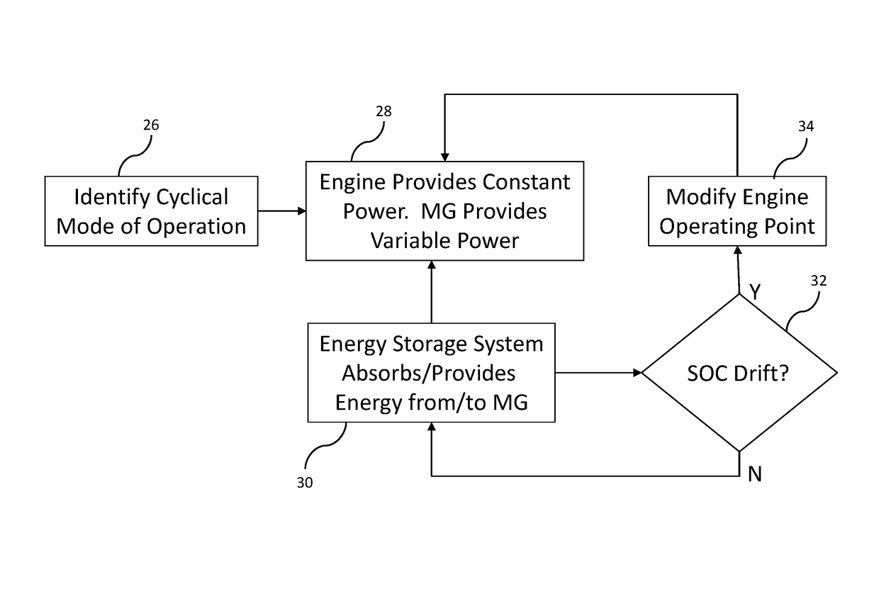
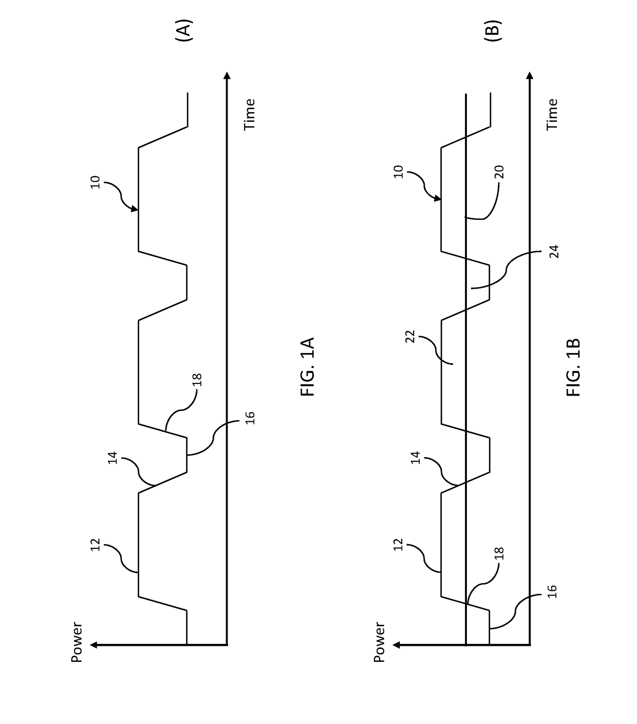
[0005]The present disclosure proposes using a motor / generator (“MG”) to provide a variable component of power required by the equipment and the engine to provide a relatively constant average power. This approach may integrate the capability to absorb excess energy when the hay baler is operating under low load conditions and to convert this energy to electrical energy for storage or immediate use. This would improve driver comfort, as he / she would not be subject to sudden jerking motion in the driver's seat / cab because the engine operates at a relatively constant power output. In one embodiment, the stored electrical energy is used to power the MG to provide the assist power during load pickup to again avoid sudden jerking motion.

Problems solved by technology

Such cyclical operation can cause driver discomfort as a result of sudden jerking motion in the driver's seat / cab when the equipment transitions between high load and low load operation.
Additionally, such cyclical operation may cause mechanical stress in the equipment and undesirable transient response.

Method used


Image

  • Method and system for controlling operation of an engine powered device having cyclical duty cycles
  • Method and system for controlling operation of an engine powered device having cyclical duty cycles
  • Method and system for controlling operation of an engine powered device having cyclical duty cycles

Examples


Embodiment Construction

[0016]The embodiment disclosed below is not intended to be exhaustive or limit the disclosure to the precise form disclosed in the following detailed description. Rather, the embodiments are chosen and described so that others skilled in the art may utilize its teachings.

[0017]One of ordinary skill in the art will realize that the embodiments provided can be implemented in hardware, software, firmware, and / or a combination thereof. For example, the electronic control module (“ECM”) disclosed herein may form a portion of a processing subsystem including one or more computing devices having memory, processing, and communication hardware. The ECM may be a single device or a distributed device, and the functions of the ECM may be performed by hardware and / or as computer instructions on a non-transient computer readable storage medium. For example, the computer instructions or programming code in the ECM may be implemented in any viable programming language such as C, C++, HTML, XTML, JA...


PUM


Abstract

A method of controlling operation of a powered device is provided, comprising determining whether the device is experiencing a cyclical load profile including high load conditions and low load conditions, applying a first power component to the device using an engine, the first power component corresponding to an average power required by the cyclical load profile, and applying a second power component to the device using a motor / generator, a sum of the first power component and the second power component corresponding to a power required by the powered device during the high load conditions.

Description

RELATED APPLICATIONS[0001]This application claims priority to U.S. Provisional Patent Application Ser. No. 62 / 197,503, filed Jul. 27, 2015, the disclosure of which is expressly incorporated herein by reference in its entirety.FIELD OF THE DISCLOSURE[0002]The present disclosure generally relates to methods and systems for controlling operation of engine powered devices, and more particularly to controlling operation of engine powered devices that experience cyclical load conditions.BACKGROUND OF THE DISCLOSURE[0003]Some off-highway equipment applications have periods of operation that are cyclical. An example of this is a tractor being used to bale hay (i.e., a baler). The baler experiences high loads as hay is being baled, but experiences low loads when the end of a row is reached and the tractor is positioned to bale the next row. This cycle between high loads and low loads repeats as the tractor traverses the field. Other examples include certain concrete pump applications (high l...

Claims


Application Information

Patent Timeline
Patent Type & Authority Patents(United States)
IPC IPC(8): B60W30/00B60W10/06A01B67/00B60W10/08B60W30/188A01F15/08
CPCB60W30/188A01B67/00B60W10/06B60W10/08B60W2710/244B60W2400/00B60W2510/244B60W2710/06A01F15/0841B60W10/30B60W20/10B60W30/1888B60W50/0097B60W2300/15B60W2510/305B60W2710/0677B60W2710/086B60W2555/20B60W2556/45B60W2556/50Y02T10/62Y02P60/14
Inventor LIGHT-HOLETS, JENNIFER K.BOOKS, MARTIN T.
Owner CUMMINS INC
Why Eureka
Try Eureka