Magnetron power supply

a power supply and magnetron technology, applied in microwave heating, electric/magnetic/electromagnetic heating, instruments, etc., can solve the problem of flickering and slowness of the material, and achieve the effect of less flickering and less illumination

Inactive Publication Date: 2018-07-31
CERAVISION LTD
View PDF12 Cites 0 Cited by
  • Summary
  • Abstract
  • Description
  • Claims
  • Application Information

AI Technical Summary

Benefits of technology

[0026]Provision of the integrated circuit as a discrete element separate from the microprocessor provides a fast control loop, which is not limited by the speed of the microprocessor. (The

Problems solved by technology

(The latter is liable to be slow due to e

Method used


Image

  • Magnetron power supply
  • Magnetron power supply
  • Magnetron power supply

Examples


Embodiment Construction

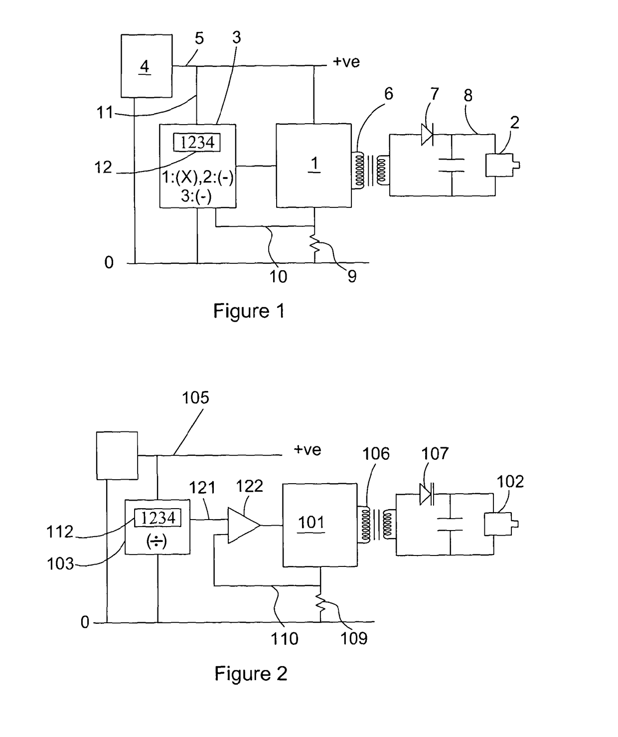
[0046]Referring first to FIG. 1, there is shown diagrammatically a prior power supply having an oscillator 1 connected to power a magnetron 2 and controlled by a microprocessor 3. An augmented mains voltage, DC voltage source 4 supplies typically 400 volts on line 5 to the oscillator 1. This feeds alternating current to a transformer 6 and rectifier 7 from which 4000 DC volts is applied on line 8 to the magnetron. The oscillator, transformer and rectifier are referred to as a “high voltage converter”. Power being supplied to the magnetron is measured in terms of the voltage across a resistor 9 in the earth return of the converter. The voltage is indicative of the current in the resistor 9 and is proportional to the power applied to the magnetron, assuming constant voltage from the voltage source 4. The resistor voltage is one input on line 10 to the microprocessor. Another input on line 11 applies the voltage on line 5 to the microprocessor. A desired power control value 12 is set e...


PUM


Abstract

A power supply for a magnetron has a high voltage converter, a microprocessor and a resistor. The high voltage converter comprises an integrated circuit oscillator, switching transistors, an inductance L1, a transformer and a rectifier. A voltage source supplies an augmented DC voltage to the converter. An operational amplifier, arranged as an error signal magnifier with an integrating capacitor and a resistor, compares a control signal from the microprocessor and the resistor and supplies an output signal to the oscillator. The oscillator controls the switching transistors, the output of which is connected to the inductance and the primary winding of the transformer. The secondary winding of the transformer is connected to half bridge diodes and capacitors, which provide DC current from the transformer to the magnetron.

Description

CROSS REFERENCE TO RELATED APPLICATION[0001]This application is for entry into the U.S. National Phase under § 371 for International Application No. PCT / GB2011 / 000920 having an international filing date of Jun. 17, 2011, and from which priority is claimed under all applicable sections of Title of the United States Code including, but not limited to, Sections 120, 363, and 365(c), and which in turn claims priority under 35 USC 119 to United Kingdom Patent Application No. 1010358.8 filed on Jun. 21, 2010.BACKGROUND OF THE INVENTION[0002]Field of the Invention[0003]The present invention relates to a power supply for a magnetron, in particular but not exclusively for use with a magnetron powering a lamp.[0004]Description of the Related Art[0005]It is known that magnetrons can change mode unexpected, that is to say that unexpectedly they can stop oscillating at one frequency and start oscillating at another. Under these conditions, they can exhibit negative impedance. This can result in ...

Claims


Application Information

Patent Timeline
IPC IPC(8): H02M3/335H05B6/68
CPCH05B6/685H02M3/33569H02M3/33571H02M3/01H05B6/68
Inventor LIDSTROM, KJELL
Owner CERAVISION LTD
Why Eureka
Try Eureka