
Electrofusion fitting methods

a technology of electrofusion and fittings, applied in the direction of corrosion prevention, pipe protection, pipe protection against corrosion/incrustation, etc., can solve problems such as power consumption drop

Active Publication Date: 2018-08-14
PIONEER LINING TECH
View PDF33 Cites 0 Cited by
  • Summary
  • Abstract
  • Description
  • Claims
  • Application Information

AI Technical Summary

Benefits of technology

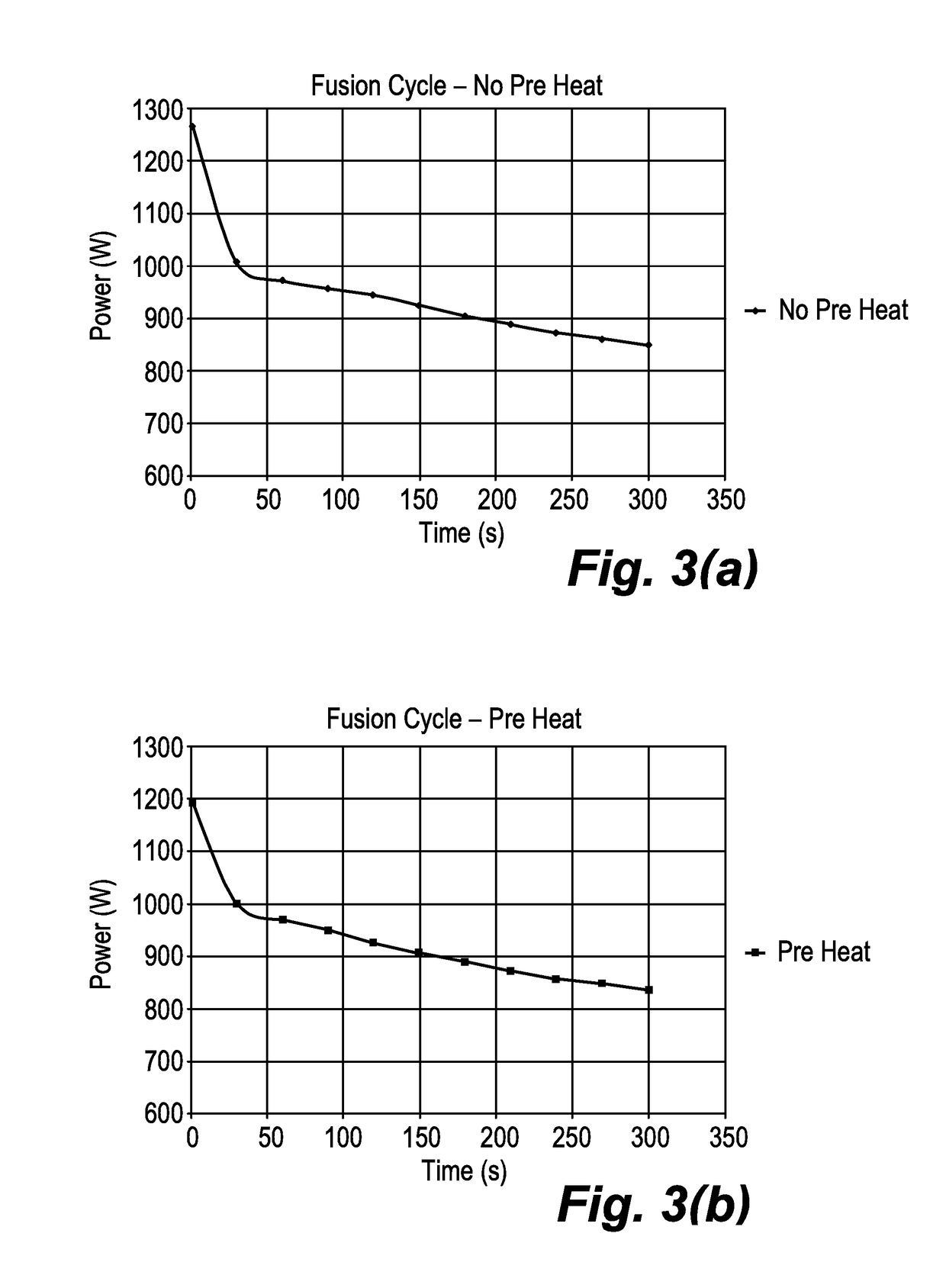
[0009]The invention provides several advantages. Firstly, the electrofusion fitting, by virtue of the initial heating step or pre-heat, can expand to improve or ensure contact between the surface of the fitting and the pipe lining. This is particularly advantageous when two lined pipe sections are aligned for welding but there is misalignment between the liners and / or the electrofusion fitting resulting in gaps there between. Expansion of the electrofusion fitting caused by the initial heating step may compensate for this misalignment by filling any such gaps between the electrofusion fitting and the pipe linings, ensuring complete contact when the weld takes place. Secondly, the initial heating step enables the subsequent welding step to be performed from the same starting temperature (or at least a known starting temperature) of the fitting and / or the pipe lining every time—meaning that the reliability of the fusion process and the likelihood of making an acceptable weld is vastly increased. Thirdly, the Applicant has found that the initial heating step improves energy coupling into heating elements, such as copper coils, during the subsequent fusion step with a resulting drop in power consumption—particularly at the outset.
[0020]This can be performed after the weld has taken place to test the integrity of the weld. However, there is a significant benefit if the leak test is performed before the weld is performed, to confirm contact between the electrofusion fitting and the pipe lining following the initial heating step. Therefore, the method may alternatively, or additionally, comprise performing the leak test before welding the fitting to the pipe lining.
[0033]The plastic pipes may be standalone, or may be liners of, e.g. carbon steel, host pipes in which case the host pipes are aligned prior to heating the electrofusion fitting to fill the recesses. As noted above in relation to the first aspect, expansion of the electrofusion fitting caused by the initial heating step can compensate for misalignment by filling any gaps between the electrofusion fitting and the plastic pipes, ensuring complete contact when the weld takes place.

Problems solved by technology

Thirdly, the Applicant has found that the initial heating step improves energy coupling into heating elements, such as copper coils, during the subsequent fusion step with a resulting drop in power consumption—particularly at the outset.

Method used


Image

  • Electrofusion fitting methods
  • Electrofusion fitting methods
  • Electrofusion fitting methods

Examples


Embodiment Construction

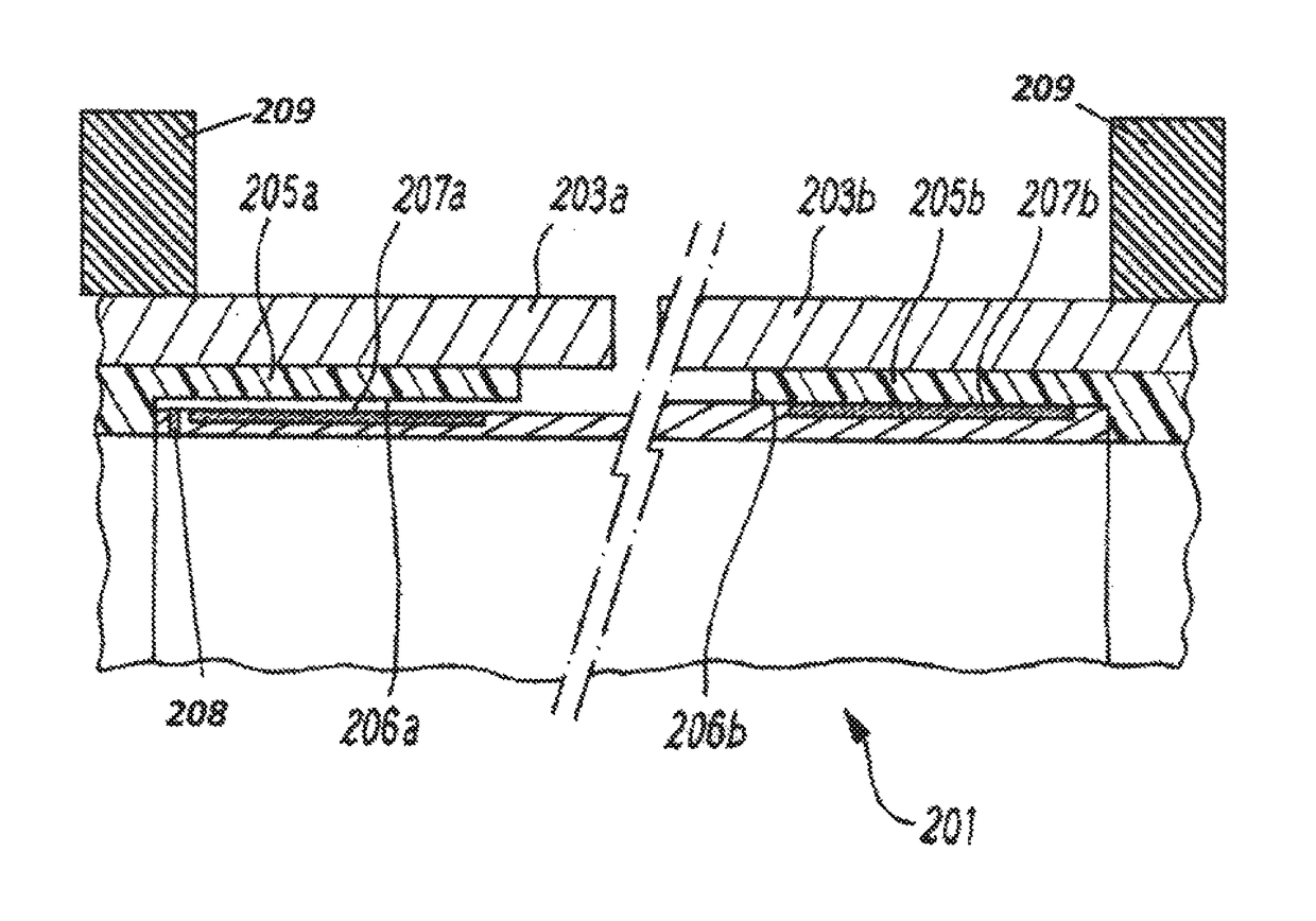
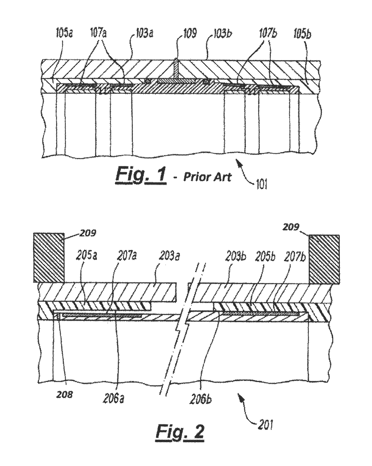
[0050]As discussed in the background to the invention above, it is difficult to ensure that an effective and consistent fusion process is carried out when connecting lined pipes or the like. An embodiment of the present invention is described below, with reference to the electrofusion fitting illustrated in FIG. 2, which overcomes this problem with the prior art.

[0051]An electrofusion fitting 201 is formed by a cylindrical sleeve of a thermoplastic material having heating coils 207a,207b disposed toward either end of the fitting 201. The electrofusion fitting 201 is shaped and sized to be inserted into the end of a lined pipe section 203a / 203b and received in a recess 206a / 206b in the end of the pipe lining 205a / 205b. The heating coils 207a / 207b are embedded in the outer surface of the fitting 201, so as to be adjacent to and facing an inner surface of the pipe lining 205a / 205b, such that when provided with sufficient electrical power the thermoplastic material of the fitting 201 an...


PUM

PropertyMeasurementUnit
temperatureaaaaaaaaaa

Abstract

The invention provides improvements to electrofusion fitting methods that allow for continuity and repeatability of welds between an electrofusion fitting and a pipe lining (or stand-alone pipe). An electrofusion fitting for joining sections of lined pipe has heating elements configured to create at least one weld between the electrofusion fitting and a pipe lining, however prior to the weld step taking place the electrofusion fitting is heated and expands accordingly to ensure contact with the pipe lining. Preheating the electrofusion fitting also provides a predetermined starting temperature for the fitting and the lining which results in improved fusion cycle reliability. Furthermore, the need for clamps or support frames to support the electrofusion fitting in situ is removed, with corresponding reductions in cycle times, complexity, and hence cost.

Description

[0001]The present invention relates to the field of electrofusion fittings such as employed to join sections of lined pipes. More specifically, the present invention concerns improvements to a method of joining sections of lined pipe with an electrofusion fitting that improves the quality and repeatability of joints formed there between.BACKGROUND TO THE INVENTION[0002]It is known that the life and performance of new and existing pipelines can be extended and optimised by lining lengths of metal pipe with polymer liners. For example, the Applicant's Swagelining® pipe lining service allows existing pipelines to be remediated and new pipelines to be provided with corrosion resistance by installing a polymer liner that remains in tight contact with the inside of a host pipe.[0003]To join adjacent lined pipe lengths, it is known to provide an electrofusion fitting to connect the inner pipe linings prior to welding the metal pipe lengths together. The Applicant's earlier International Ap...

Claims


Application Information

Patent Timeline
Patent Type & Authority Patents(United States)
IPC IPC(8): F16L47/03B29C65/34B29C65/82B29C65/00F16L58/18B29K101/12B29K105/00
CPCF16L47/03B29C65/3468B29C65/8246B29C66/0242B29C66/1224B29C66/5221B29C66/72321B29C66/91411B29C66/91655B29C66/91935B29C65/3432F16L58/181B29C65/342B29C65/3476B29C66/1142B29C66/1222B29C66/1282B29C66/1286B29C66/12842B29C66/14B29C66/232B29C66/5229B29C66/52293B29C66/52296B29C66/534B29C66/612B29C66/7392B29C66/919B29C66/91221B29C66/91445B29C66/91921B29C66/942B29C66/944B29C66/949B29K2101/12B29K2105/258B29C66/1122B29C66/63B29C66/723
Inventor BARNES, STEPHEN
Owner PIONEER LINING TECH
Learn More