
Method for accurately aligning and correcting images in high dynamic range video and image processing

a high dynamic range video and image processing technology, applied in image analysis, image enhancement, instruments, etc., can solve problems such as misalignment of ldr images, and achieve the effect of accurately aligning and correcting images

Inactive Publication Date: 2018-08-14
PINNACLE IMAGING
View PDF1 Cites 7 Cited by
  • Summary
  • Abstract
  • Description
  • Claims
  • Application Information

AI Technical Summary

Benefits of technology

The invention provides a better way to align and fix pictures in high dynamic range video and image processing. It helps to overcome the problems of the previous method.

Problems solved by technology

This requires taking images at different shot times, which can cause misalignment of the LDR images when the camera was moving or shaking during shots (i.e. cameras without a tripod).

Method used


Image

  • Method for accurately aligning and correcting images in high dynamic range video and image processing
  • Method for accurately aligning and correcting images in high dynamic range video and image processing
  • Method for accurately aligning and correcting images in high dynamic range video and image processing

Examples


Embodiment Construction

[0033]Reference will now be made in detail to the preferred embodiments of the present invention, examples of which are illustrated in the accompanying drawings. Wherever possible, the same reference numbers are used in the drawings and the description to refer to the same or like parts.

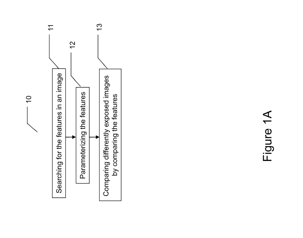
[0034]Refer to FIG. 1A, which is a flowchart illustrating an alignment method for high dynamic range imaging according to an embodiment of the present invention.

[0035]The method 10, begins in Step 11 by searching for the features (characterizing elements) in an image. Next, in Step 12 the method continues with a step of parameterization of those features. And Step 12 comprises a step of comparison of differently exposed images by comparing the features.

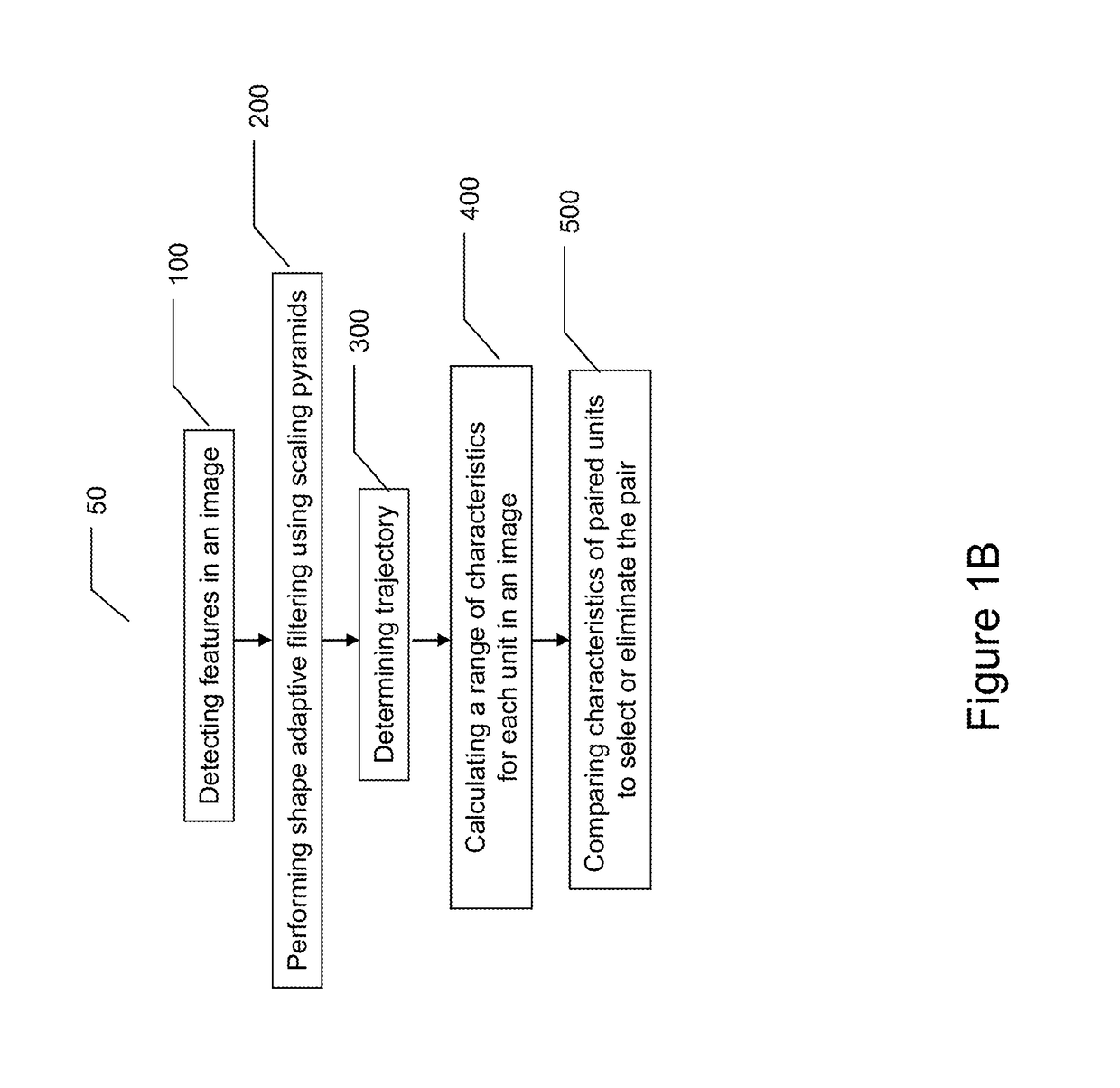
[0036]Refer to FIG. 1B, which is a flowchart illustrating an alignment method for high dynamic range imaging according to an embodiment of the present invention.

[0037]The method 50 begins in Step 100, by detecting features in an image.

[0038]In order to...


PUM


Abstract

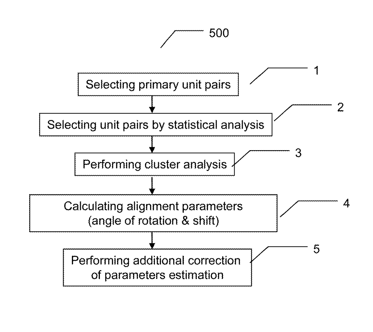
An alignment method for high dynamic resolution imaging searches and detects features in an image and parameterizing the features. Then differently exposed images are compared by comparing the features. Additionally the method detects features in an image, performs shape adaptive filtering using scaling pyramids, determines trajectories, calculates a range of characteristics for each unit in the image, and compares characteristics of paired units to select or eliminate the pair. Paired unit characterization selects unit pairs, selects unit pairs by statistical analysis, performs cluster analysis, calculates alignment parameters, and performs additional correction of the alignment parameters. The brightness channel is used for objects detection.

Description

BACKGROUND OF THE INVENTIONField of the Invention[0001]The present invention relates to digital imaging. More specifically, the present invention discloses a method for accurately aligning and correcting images in high dynamic range video and image processing.Description of the Prior Art[0002]High dynamic range imaging is used to reproduce a greater dynamic range of luminosity in imaging and photography. A conventional technique of high dynamic range imaging includes utilizing special image sensors for oversampling. Another technique involves merging multiple images.[0003]However, the special image sensors often encounter difficulty when used in low light conditions which produces a non-optimal resultant image. Additionally, digital image encoding does not always offer a great enough range of values to allow fine transitions which causes undesirable effects due to lossy compression.[0004]Therefore, there is need for an efficient alignment method for accurately aligning and correctin...

Claims


Application Information

Patent Timeline
Patent Type & Authority Patents(United States)
IPC IPC(8): G06K9/32G06T7/33G06T7/00G06T7/35
CPCG06T7/344G06T7/97G06T7/35G06T2207/20208G06T5/50G06T2207/10016G06T7/33G06T5/92G06V10/758G06V10/751H04N23/741G06T5/90
Inventor MARKOVA, ELENA ALEKSANDROVNAGRIGOR'EVICH, KLIMKOVICH ANTONVALER'EVICH, VANJUSHIN IGOR'
Owner PINNACLE IMAGING
Learn More