Cutting heads and agricultural seeder implements formed therewith

a technology of agricultural seeder implements and cutting heads, which is applied in the direction of direct liquid fertiliser delivery, furrow making/covering, agriculture, etc., can solve the problems of slow soil fertilizer distribution, delay the ability of the roots of germinated and inherently limited ability of planted seeds to reach fertilizer

Active Publication Date: 2018-08-21
KILE RONALD J
View PDF9 Cites 1 Cited by
  • Summary
  • Abstract
  • Description
  • Claims
  • Application Information

AI Technical Summary

Benefits of technology

[0003]According to the principle of the invention, an agricultural implement for working soil across which the agricultural implement travels or is towed includes a mount, a head having a trailing extremity mounted on the mount and a leading extremity for cutting into soil ahead of the mount, and a fertilizer tube extending through the head to a discharge end for discharging a stream of fertilizer into the soil from the head. A shield is mounted on the mount above the head. The shield spans a length of the fertilizer tube above the head for protecting the length of the fertilizer tube from soil and rocks and agricultural crop material. In a first embodiment, the discharge end of the fertilizer tube is proximate to the leading extremity for discharging the stream of fertilizer from the leading extremity. The head further includes opposed upper and lower ends, and a leading bulk that extends from the upper end to the leading extremity proximate to the lower end. In the first embodiment, the fertilizer tube extends through the leading bulk from the upper end to the leading extremity. In the first embodiment, the leading extremity includes opposed first and second sides and a knife extending outwardly from one of the first and second sides, and the fertilizer tube extends through the knife to the discharge opening for discharging the stream of fertilizer into the soil from the knife. The knife is swept back from the leading extremity. In a second embodiment, the discharge end of the fertilizer tube is proximate to the trailing extremity for discharging the stream of fertilizer from the trailing extremity. In the second embodiment, the head further includes a trailing bulk that extends along the lower end of the head from the leading extremity to the trailing extremity, and the fertilizer tube extends through the leading bulk from the upper end to the leading extremity and through the lower bulk from the leading extremity to the trailing extremity.
[0004]According to the principle of the invention, an agricultural implement for working soil across which the agricultural implement travels or is towed includes a mount, a head having a trailing extremity mounted on the mount and a leading extremity including opposed first and second sides, the leading extremity for cutting into soil ahead of the mount, a first fertilizer tube extending through the head to a first discharge end for discharging a first stream of fertilizer into the soil from the head relative to the first side of the leading extremity, and a second fertilizer tube extending through the head to a second discharge end for discharging a second stream of fertilizer into the soil from the head relative to the second side of the leading extremity. The head further includes opposed upper and lower ends, and a leading bulk extending from the upper end to the leading extremity proximate to the lower end. The first and second fertilizer tubes extend through the leading bulk from the upper end to the leading extremity. A shield mounted on the mount above the upper end of the head spans lengths of the respective first and second fertilizer tubes above the upper end of the head for protecting the lengths of the respective first and second fertilizer tubes from soil and rocks and agricultural crop material.
[0005]According to the principle of the invention, an agricultural implement for working soil across which the agricultural implement travels or is towed includes a mount, a head having a trailing extremity mounted on the mount and a leading extremity including opposed first and second sides, a first knife extending outwardly from the first side of the leading extremity, and a second knife extending outwardly from the second side of the leading extremity, the leading extremity for cutting into soil ahead of the mount, a first fertilizer tube extending through the head to a first discharge end at the first knife for discharging a first stream of fertilizer into the soil from the first knife, and a second fertilizer tube extending through the head to a second discharge end at the second knife for discharging a second stream of fertilizer into the soil from the second knife. The first and second knives are swept back from the leading extremity. The head further includes opposed upper and lower ends, a leading bulk that extends from the upper end to the leading extremity proximate to the lower end, and the first and second fertilizer tubes extend through the leading bulk from the upper end to the respective first and second knives of the leading extremity. A shield mounted on the mount above the upper end of the head spans lengths of the respective first and second fertilizer tubes above the upper end of the head for protecting the lengths of the respective first and second fertilizer tubes from soil and rocks and agricultural crop material.

Problems solved by technology

Until the applied fertilizer is dissolved and carried down into the soil to the planted seeds through the application of water, whether from rain or watering, the ability of the roots of the planted seeds to reach the fertilizer is inherently limited.
Furthermore, conventional openers of agricultural seeder implements can fail to sufficiently disrupt and aerate the soil during furrow formation, especially when the soil is hard or compacted, which can inherently delay the ability of the roots of the germinated seeds from taking root, and slow the distribution of the fertilizer into the soil.

Method used


Image

  • Cutting heads and agricultural seeder implements formed therewith
  • Cutting heads and agricultural seeder implements formed therewith
  • Cutting heads and agricultural seeder implements formed therewith

Examples


Embodiment Construction

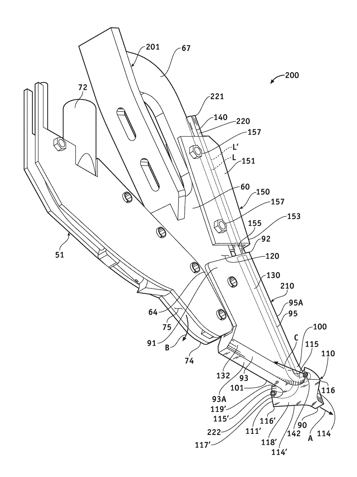
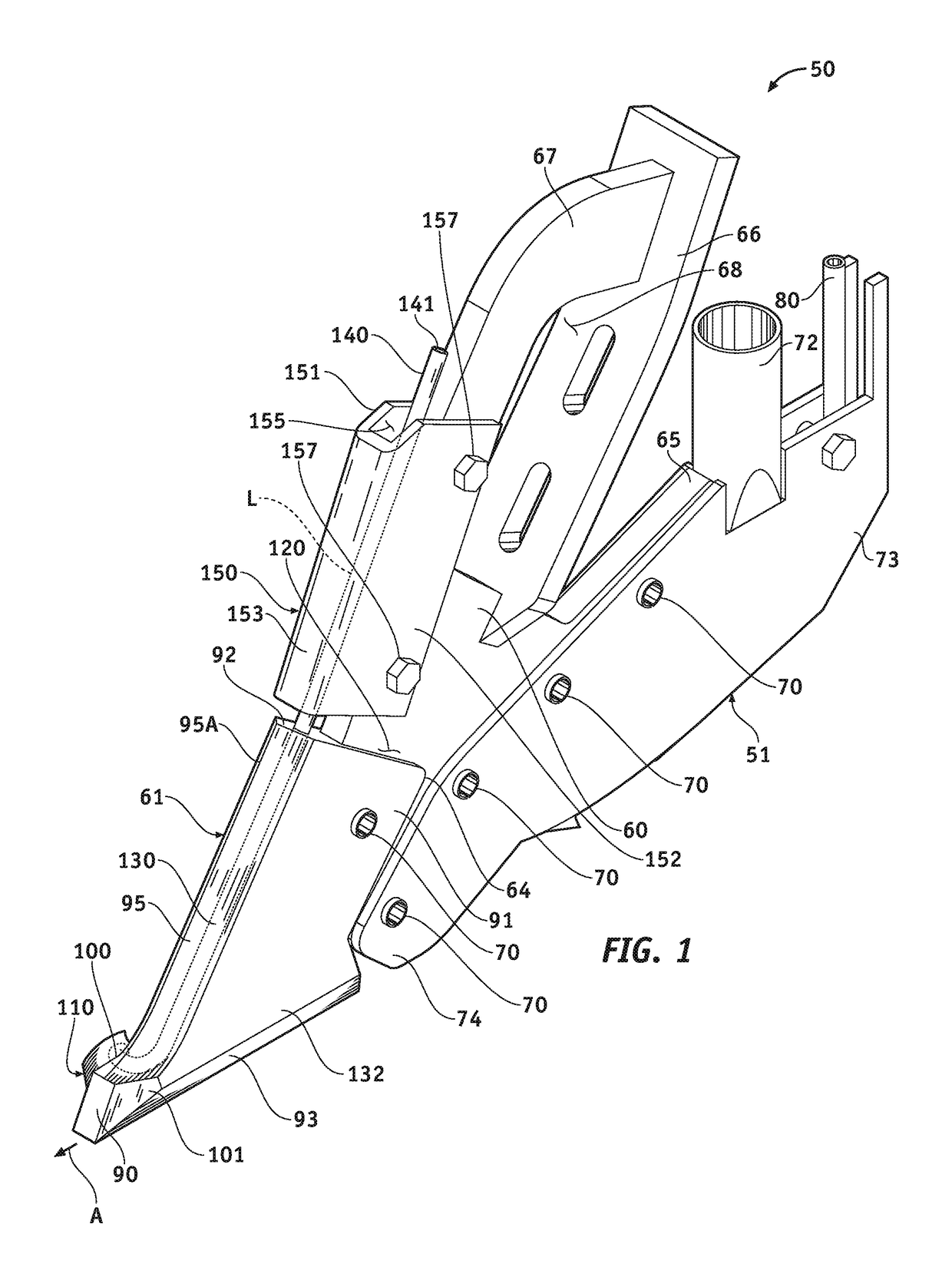
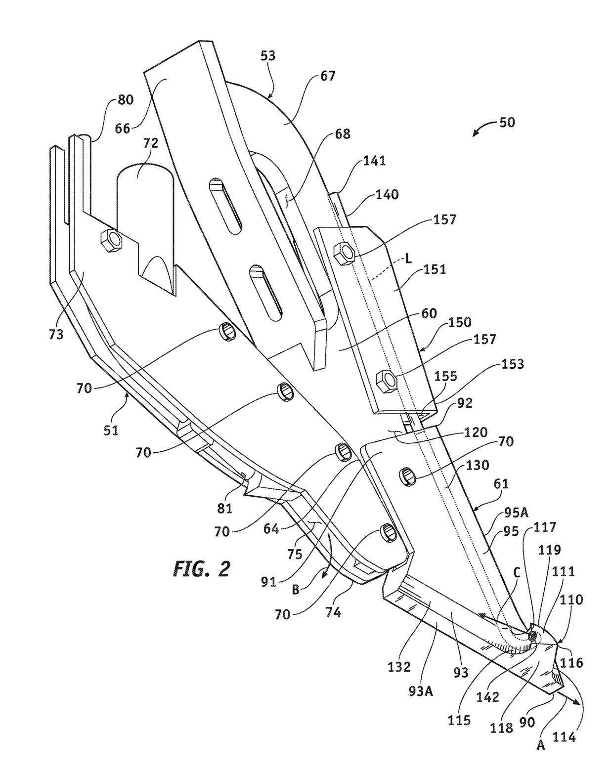
[0046]Turning now to the drawings, in which like reference characters indicate corresponding elements throughout the several views, attention is first directed to FIGS. 1, 2, and 7 in which there is seen an agricultural seeder implement 50 constructed and arranged in accordance with the principle of the invention. Implement 50 includes seed boot 51 and opener 53. Opener 53 is connected to seed boot 51. Opener 53 is configured to be connected to a shank of a plow frame for suspending implement 50 from the shank, which, when advanced in the direction of arrowed line A leading with opening 53, enables implement 50 to work the soil for sowing a crop. Opener 53 is a chisel, being a non-moving and non-rotating opener for being advanced by a tractor for cutting a furrow in the ground at a chosen depth from the surface of the ground, and seed boot 51 connected to opener 53 is for receiving a stream of air-driven seed and depositing the stream of air-driven seed into the furrow formed by ope...


PUM


Abstract

A soil cutting head for a mount of an agricultural implement includes a head having a leading extremity for cutting into soil ahead of the mount, and a fertilizer tube extending through the head to a discharge end for discharging a stream of fertilizer into the soil from the head.

Description

FIELD OF THE INVENTION[0001]The present invention relates to agricultural implements and, more particularly, to a soil opener for an agricultural seeder implement for simultaneously cutting and depositing fertilizer into soil.BACKGROUND OF THE INVENTION[0002]In an agricultural seeder implement, seeds are conveyed by an air stream from a hopper to a number of seeding elements, carried by a frame, that inject the seed into furrows cut into the ground by openers incorporated with the seeding elements. During the seeding process, fertilizer banding is customary, which is the concurrent application of a fertilizer adjacent to but spaced from the applied seeds so that once germination has occurred the roots can access the fertilizer. Customarily, the seed is applied to the furrow first followed by the fertilizer, which inherently results in the application of the fertilizer above the applied seeds. Until the applied fertilizer is dissolved and carried down into the soil to the planted see...

Claims


Application Information

Patent Timeline
Patent Type & Authority Patents(United States)
IPC IPC(8): A01C5/06A01C7/00A01C23/02A01C15/00
CPCA01C5/062A01C23/025A01C7/00A01C15/006A01C7/06A01C7/206
Inventor KILE, RONALD J.
Owner KILE RONALD J
Why Eureka
Try Eureka