Transfer pump launder system

a technology of transfer pump and transfer pump, which is applied in the direction of machines/engines, manufacturing tools, liquid fuel engines, etc., can solve the problems of molten metal interaction, safety hazards, and use of most transfer pumps

Active Publication Date: 2018-08-21
MOLTEN METAL EQUIP INNOVIATIONS LLC
View PDF705 Cites 43 Cited by
  • Summary
  • Abstract
  • Description
  • Claims
  • Application Information

AI Technical Summary

Benefits of technology

The present invention is about a transfer pump used to move molten metal out of a container. The pump is a standard one that has a riser tube that extends above the surface of the metal bath. This helps to create a smooth and smooth flow of the metal, without any turbulence.

Problems solved by technology

There are problems with each of these known methods.
This turbulence causes the molten metal to interact more with the air than would a smooth flow of molten metal pouring into the ladle.
The interaction with the air leads to the formation of dross within the ladle and splashing also creates a safety hazard because persons working near the ladle could be hit with molten metal.
Further, there are problems inherent with the use of most transfer pumps.
The blockage blocks the flow of molten metal through the pump and essentially causes a failure of the system.
This causes hours of expensive downtime.
The molten metal in the piping can also solidify causing failure of the system and downtime associated with replacing the piping.
Use of a tap-out hole at the bottom of a furnace can lead to problems.
First, when the tap-out plug is removed molten metal can splash or splatter causing a safety problem.
This is particularly true if the level of molten metal in the furnace is relatively high which leads to a relatively high pressure pushing molten metal out of the tap-out hole.
There is also a safety problem when the tap-out plug is reinserted into the tap-out hole because molten metal can splatter or splash onto personnel during this process.
Further, after the tap-out hole is plugged, it can still leak.
The leak may ultimately cause a fire, lead to physical harm of a person and / or the loss of a large amount of molten metal from the furnace that must then be cleaned up, or the leak and subsequent solidifying of the molten metal may lead to loss of the entire furnace.
Another problem with tap-out holes is that the molten metal at the bottom of the furnace can harden if not properly circulated thereby blocking the tap-out hole or the tap out hole can be blocked by a piece of dross in the molten metal.

Method used


Image

  • Transfer pump launder system
  • Transfer pump launder system
  • Transfer pump launder system

Examples


Embodiment Construction

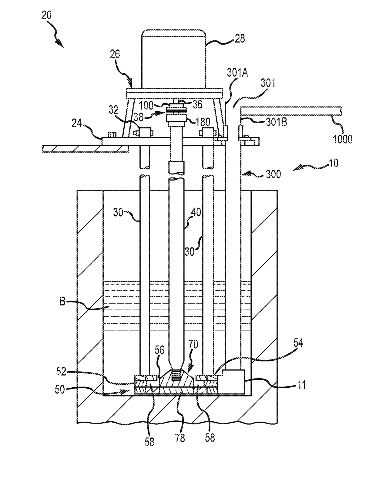
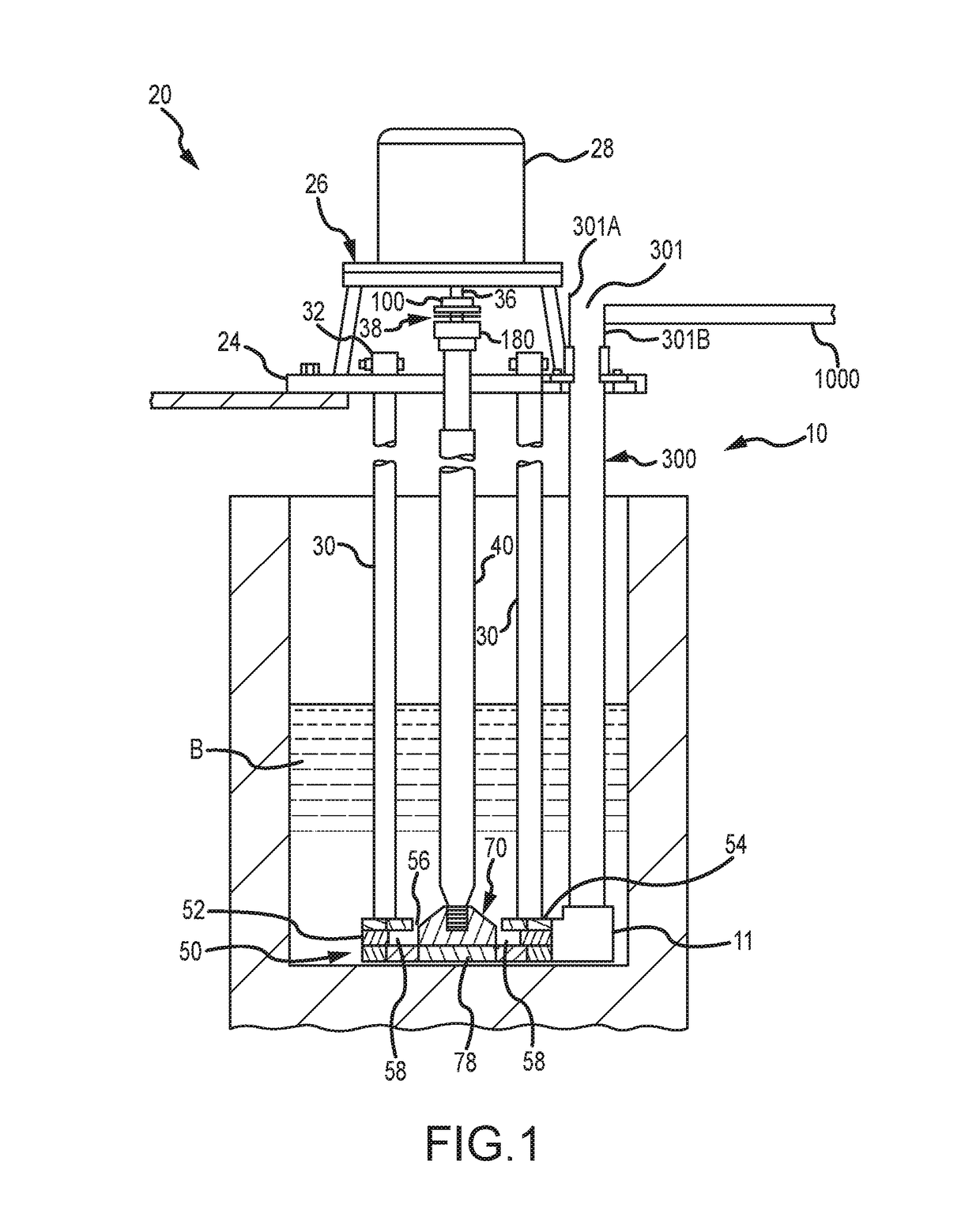
[0027]Referring now to the figures, where the purpose is for describing a preferred embodiment of the invention and not for limiting same, FIG. 1 shows a pumping device 10 submerged in a metallic bath B. Device 10 has a superstructure 20 and a base 50. Superstructure 20 is positioned outside of bath B when device 10 is operating and generally comprises a mounting plate 24 that supports a motor mount 26. A motor 28 is mounted to mount 26. Motor 28 is preferably electric or pneumatic although, as used herein, the term motor refers to any device capable of driving a rotor 70.

[0028]Superstructure 20 is connected to base 50 by one or more support posts 30. Preferably posts 30 extend through openings (not shown) in plate 24 and are secured by post clamps 32, which are preferably bolted to the top surface (preferred) or lower surface of plate 24.

[0029]A motor drive shaft 36 extends from motor 28. A coupling 38 has a first coupling member 100, attached to drive shaft 36, and a second coupli...


PUM

PropertyMeasurementUnit
lengthaaaaaaaaaa
lengthaaaaaaaaaa
lengthaaaaaaaaaa

Abstract

A pump having a motor, a pump base with a pump chamber, a tangential discharge and an outlet in the pump base. A riser tube extends upward from the outlet and terminates at or above a launder in order to move molten metal out of a vessel with relatively little turbulence.

Description

FIELD OF THE INVENTION[0001]The present invention relates generally to transfer pumps and transfer pumps that generate a small amount of turbulence by having a riser tube that terminates at a launder above the molten metal bath in which the pump rate is submerged.BACKGROUND[0002]As used herein, the term “molten metal” means any metal or combination of metals in liquid form, such as aluminum, copper, iron, zinc and alloys thereof. The term “gas” means any gas or combination of gases, including argon, nitrogen, chlorine, fluorine, freon, and helium, that are released into molten metal.[0003]Known molten-metal pumps include a pump base (also called a housing or casing), one or more inlets (an inlet being an opening in the housing to allow molten metal to enter a pump chamber), a pump chamber, which is an open area formed within the housing, and a discharge, which is a channel or conduit of any structure or type communicating with the pump chamber (in an axial pump the chamber and disch...

Claims


Application Information

Patent Timeline
Patent Type & Authority Patents(United States)
IPC IPC(8): B22D45/00F04D29/60F04D7/06
CPCB22D45/00F04D29/607F04D7/065Y10T137/85978
Inventor COOPER, PAUL V.
Owner MOLTEN METAL EQUIP INNOVIATIONS LLC
Why Eureka
Try Eureka