Method for additive manufacturing using filament shaping

a technology of additive manufacturing and filament, applied in the direction of additive manufacturing process, manufacturing tools, manufacturing data acquisition/processing, etc., can solve the problems of ineffective stress transfer from the resin matrix to the fibers, premature failure of the part via crack propagation, void space or bubble between the fiber and the resin, etc., to improve heat transfer and bonding, improve inter-laminar strength, and improve the effect of bonding

Active Publication Date: 2018-08-21
STRATSYS INC
View PDF97 Cites 20 Cited by
  • Summary
  • Abstract
  • Description
  • Claims
  • Application Information

AI Technical Summary

Benefits of technology

[0016]Compared to the prior-art processes, embodiments in accordance with the present provide certain advantages. For example, with respect to processing fiber-composite feedstocks via a heated nozzle, the loss of wetting and fiber breakage issues that plague such processes are substantially avoided. In particular, because the filament material is not completely melted, resin does not flow out of the carbon fiber. This prevents or reduces the loss of wetting associated with complete melting as in the prior art.
[0023]At the same time, embodiments of the invention avoid the problems associated with depositing a composite filament through a heated nozzle (loss of wetting, etc.). Additionally, better inter-laminar strength is achieved than in the prior art since additional polymer-bonding mechanisms are utilized. In particular, the polymer is more thoroughly intermixed with the substrate improving heat transfer and bonding. Furthermore, controlling the compaction force (via positioning of a robotic arm, etc.) in accordance with embodiments of the invention enables the width (and thickness) of a deposited filament to be varied, as needed, rather than being limited by a fixed tape width, as in the AFP, ATL, or FW processes.

Problems solved by technology

A low degree of wetting means the fibers are not completely coated by resin, resulting in void space or bubbles between the fiber and resin.
Fiber pullout results in ineffective stress transfer from the resin matrix to the fibers due to the void space at the fiber / resin interfaces.
The void space acts as nucleating sites for cracks, resulting in premature failure of the part via crack propagation.
Thermosets typically have a low viscosity compared to other polymers, resulting in high melt flow and a high degree of fiber wetting.
While thermoset resins provide sufficient wetting, they cannot tolerate higher operating temperatures, often limited to 100° C. or less.
As compared to thermosets, thermoplastics generally have a higher viscosity, making it more difficult to achieve sufficient fiber wetting; however, thermoplastics offer higher tensile strength and stiffness, higher toughness, and a higher operating temperature as compared to thermoset resins.
As the continuous filament is pushed through the nozzle, the pressure of the nozzle forces the polymer underneath the continuous carbon fiber tow, which can result in exposed fiber on the top surface.
In addition to a loss of wetting, this type of deposition involves a 90-degree bend between the nozzle and part being manufactured, which can cause fiber breakage and damage.
The twisting and tangling of the fibers can cause them to break, reducing the overall strength and stiffness of the deposited material.
The twisting and tangling further reduces the wetting of the fibers and also produces an uneven, rough surface finish.
Furthermore, it would be undesirable to alter the cross section, because this would change the positioning of the tape.
These tapes are limited in their ability to be “steered” or turned in-plane, driving the industry towards narrower and narrower tapes (to enable a measure of steering) while maintaining their thickness.
This process is functionally limited to producing objects with relatively large curvatures, wherein only minimal steering of the tape is possible.
Furthermore, the ability to apply process heat to the incoming material is severely limited, making in-situ consolidation of high-temperature thermoplastics exceedingly difficult.
The prior-art processes discussed above cannot manufacture parts in such fashion or with such surface features or, as in the case with additive manufacturing through a heated nozzle, are likely to result in objects having compromised final properties.

Method used


Image

  • Method for additive manufacturing using filament shaping
  • Method for additive manufacturing using filament shaping
  • Method for additive manufacturing using filament shaping

Examples


Embodiment Construction

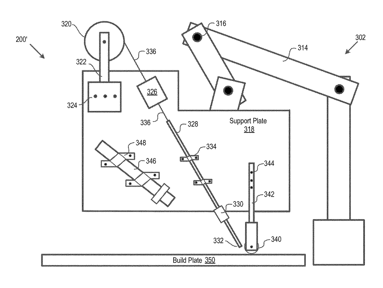
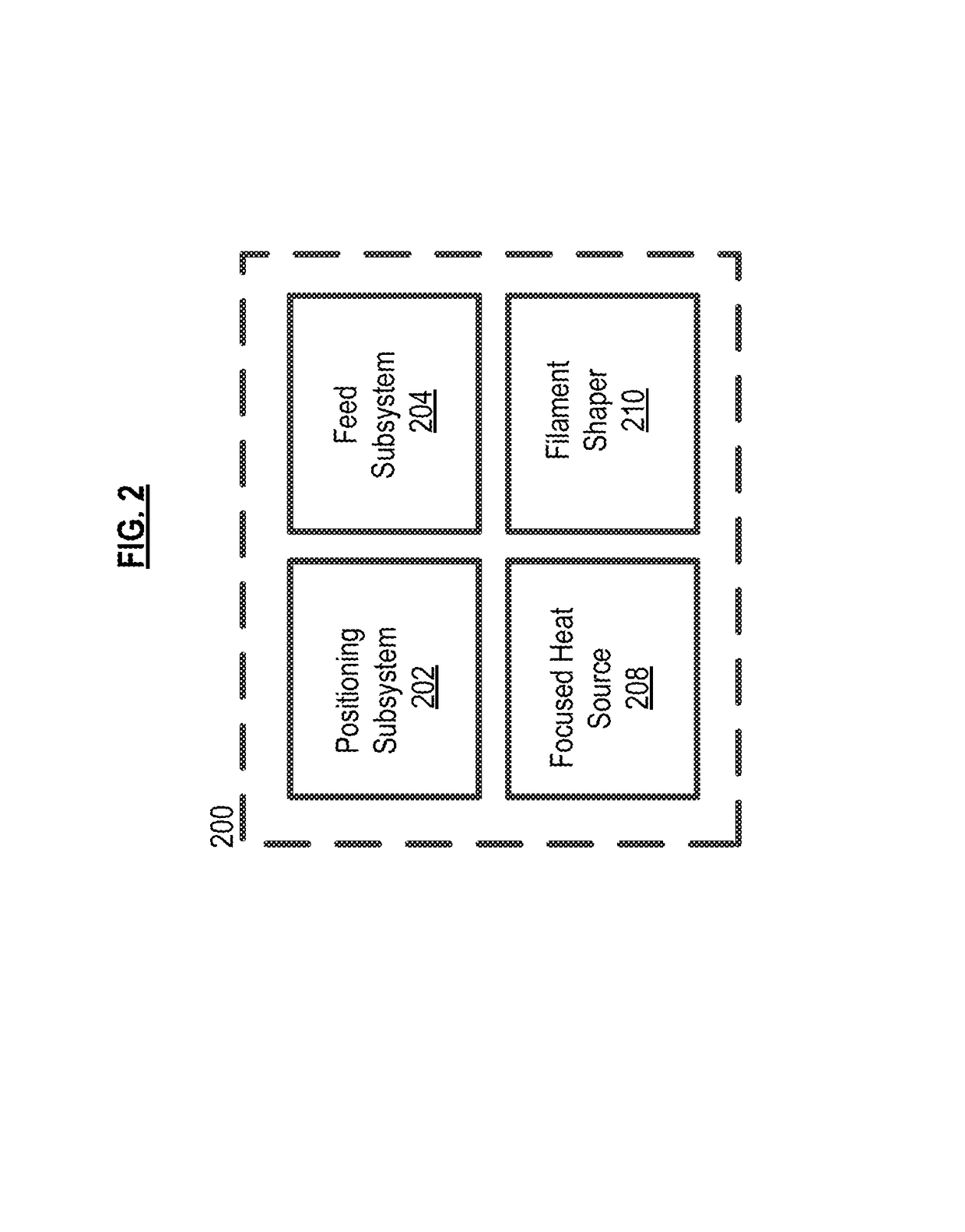
[0029]FIG. 2 depicts the salient functional elements of deposition system 200 in accordance with the present invention. Included in system 200 are positioning subsystem 202, feed subsystem 204, focused heat source 206, and shaper 210.

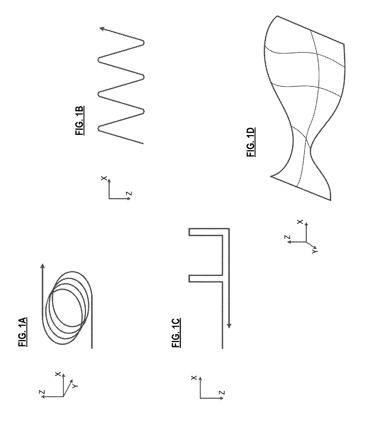
[0030]In the illustrative embodiment, positioning subsystem 202 comprises a multi-axis end effector (e.g., robotic arm, etc.). In the illustrative embodiment, the multi-axis end effector has sufficient degrees of freedom (i.e., six DOF) to enable true three-dimensional printing. That is, the positioning subsystem is capable of delivering a feed filament to an arbitrary location in space, as specified in accordance with the build instructions. This enables system 200 to print along the natural loading contours of an part. Printing with such a multi-axis end effector is described, for example, in Ser. No. 14 / 184,010, previously referenced and incorporated by reference herein.

[0031]In some other embodiments, positioning subsystem 202 comprises a gantry hav...


PUM

PropertyMeasurementUnit
operating temperaturesaaaaaaaaaa
aspect ratioaaaaaaaaaa

Abstract

A method and apparatus for additive manufacturing wherein a fiber composite filament having an arbitrarily shaped cross section is softened and then flattened to tape-like form factor for incorporation into a part that is being additively manufactured.

Description

CROSS-REFERENCE TO RELATED APPLICATIONS[0001]This case claims priority of U.S. patent application Ser. No. 62 / 314,000 filed Mar. 28, 2016, which is incorporated by reference herein.FIELD OF THE INVENTION[0002]The present invention generally relates to an additive manufacturing process using fiber composites.BACKGROUND OF THE INVENTION[0003]Additive manufacturing—so called “3D printing”—is the term given to processes that manufacture objects via sequential-layer material addition / joining throughout a 3D work envelope under automated control. ISO / ASTM52900-15 defines seven categories of additive manufacturing processes: binder jetting, directed energy deposition, material extrusion, material jetting, powder bed fusion, sheet lamination, and vat polymerization.[0004]Composite 3D printing processes produce an object or part (hereinafter collectively “part”) by depositing composite filaments made of continuous fiber-reinforced thermoplastics, which quickly harden to form a layer. Success...

Claims


Application Information

Patent Timeline
Patent Type & Authority Patents(United States)
IPC IPC(8): B29C64/141B29C64/188B33Y50/02B33Y10/00B33Y30/00B29C64/268B29C64/218B29K101/12B29K105/08
CPCB33Y10/00B33Y30/00B33Y50/02B29C64/141B29C64/188B29K2105/08B29C64/218B29C64/268B29K2101/12B29C70/384B29C64/118B29C64/20B29C64/393
Inventor ARMIJO, ARMANDOBHEDA, HEMANTMANTHA, CHANDRASHEKARMONDESIR, WIENERNANDU, SOHILREESE, RILEY
Owner STRATSYS INC
Why Eureka
Try Eureka