
Device for thermal compression of a gaseous fluid

a gaseous fluid and thermal compression technology, applied in the direction of machine/engine, engine components, engine seals, etc., can solve the problems of limiting the service life of such compressors or requiring regular maintenance, so as to reduce maintenance requirements, improve performance, and increase service life

Active Publication Date: 2018-08-21
BOOSTHEAT
View PDF8 Cites 2 Cited by
  • Summary
  • Abstract
  • Description
  • Claims
  • Application Information

AI Technical Summary

Benefits of technology

This patent text describes a regenerative thermal compressor that aims to improve performance and reduce maintenance requirements. The compressor should have a longer service life and should require less maintenance. Additionally, it should have better heat exchanges within the compressor and should improve the movement of the displacing piston. The goal is to create a competitive and easy-to-manufacture industrial-scale compressor that provides improved performance.

Problems solved by technology

The displacing piston and / or the associated control rod are subject to friction and wear, which limits the service life of such compressors or which requires regular maintenance.

Method used


Image

  • Device for thermal compression of a gaseous fluid
  • Device for thermal compression of a gaseous fluid
  • Device for thermal compression of a gaseous fluid

Examples


Embodiment Construction

[0091]In the various figures, the same references designate identical or similar elements,

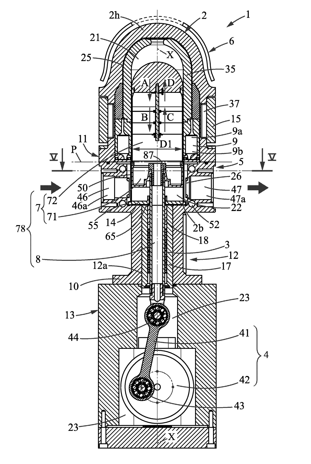
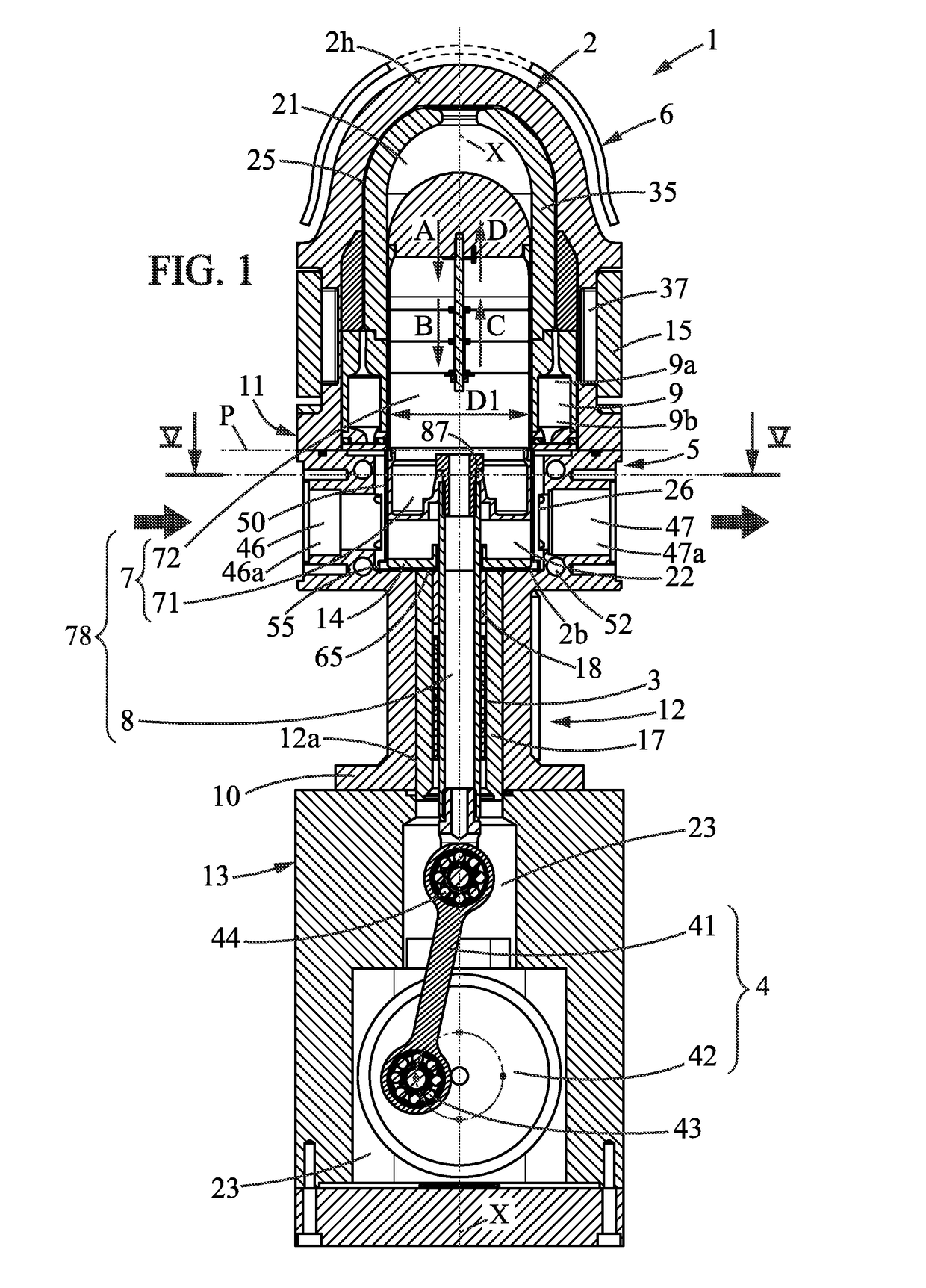
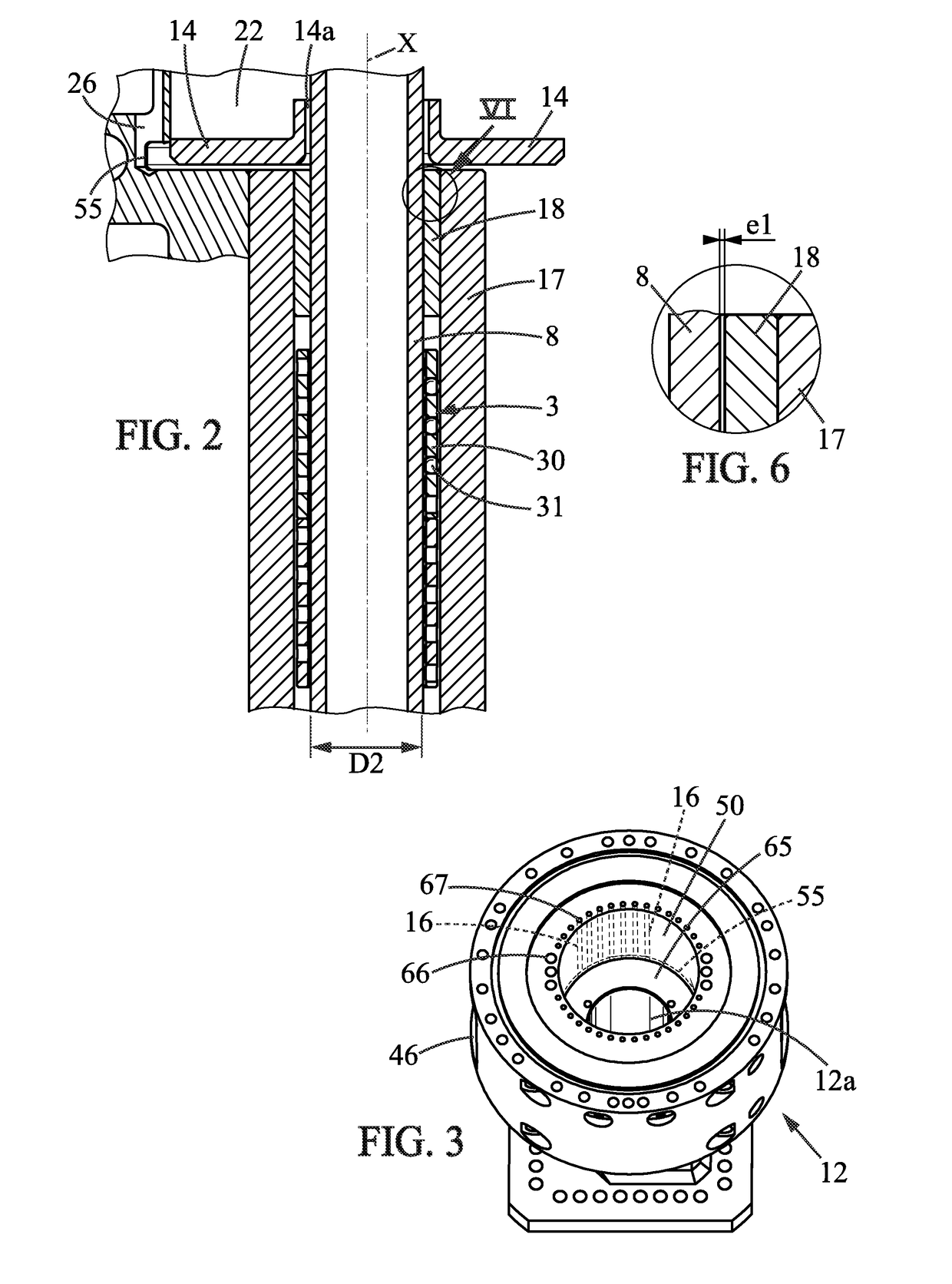
[0092]FIG. 1 shows a device 1 for compression of a gaseous fluid, adapted for admitting a gaseous fluid (also called “working fluid”) through an inlet or intake 46 at a pressure P1, and supplying the compressed fluid at pressure P2 at an outlet denoted 47.

[0093]As represented in FIGS. 1 to 12, the device is designed around an axial direction X, which is preferably oriented vertically, but this does not exclude another arrangement. A piston 7 is mounted so as to be movable along this axis at least within a cylindrical sleeve 50. Said piston hermetically separates two enclosed spaces, respectively referred to as the first chamber 21 and second chamber 22, these two chambers being contained within a work enclosure 2 that is hermetic (except for said inlets / outlets). The work enclosure 2 has an upper end 2h and a lower end 2b. The piston has a dome-shaped upper portion, for example hemispherical.

[0...


PUM


Abstract

A device for compressing a gaseous fluid includes a first chamber thermally coupled with a hot source, a second chamber thermally coupled with a cold source, a movable piston moved by a rod, and a regenerating exchanger establishing fluid communication between the first and second chambers. The rod is arranged in a cylindrical socket and guided in axial translation by a linear guiding system such as to guide the piston without contact relative to the sleeve. A sealing ring attached to the cylindrical socket surrounds the rod with a very low radial clearance, in order to limit the passage of the gaseous fluid along the mobile rod. Also disclosed is an integral cold casing having machined boreholes, a thermal screen in the hot casing, and a self-driving system with a resilient return means.

Description

BACKGROUND[0001]Technical Field[0002]The present invention relates to gaseous fluid compression devices, and deals in particular with regenerative thermal compressors.[0003]Description of the Related Art[0004]Several technical solutions already exist for compressing a gas using a heat source.[0005]In thermal compressors such as those disclosed in U.S. Pat. No. 2,157,229 and U.S. Pat. No. 3,413,815, the heat received is directly transmitted to the fluid to be compressed, thereby eliminating any mechanical element for the steps of compression and discharge.[0006]In U.S. Pat. No. 2,157,229 and U.S. Pat. No. 3,413,815, a displacing piston (‘displacer’) is movably mounted inside a chamber so as to alternately displace the fluid toward the heat source or toward the cold source. The displacing piston is connected to a control rod. The displacing piston and / or the associated control rod are subject to friction and wear, which limits the service life of such compressors or which requires reg...

Claims


Application Information

Patent Timeline
Patent Type & Authority Patents(United States)
IPC IPC(8): F02G1/057F02G1/053
CPCF02G1/057F02G1/0535F02G2280/50F02G2253/80F02G2253/03
Inventor JOFFROY, JEAN-MARCBIDAR, MARTINDANDO, LUC
Owner BOOSTHEAT
Learn More