Supercharge Your Innovation With Domain-Expert AI Agents!

Module and system for, and method of, directing an aiming pattern on, and illuminating, a target to be electro-optically read by image capture

a technology of image capture and imaging module, which is applied in the direction of sensing record carriers, instruments, and sensing by electromagnetic radiation, etc., can solve the problems of increasing the overall size, complexity and cost of manufacturing and assembling imaging modules and readers, requiring more frequent recharging, and requiring more downtim

Active Publication Date: 2018-08-21
SYMBOL TECH LLC
View PDF15 Cites 1 Cited by
  • Summary
  • Abstract
  • Description
  • Claims
  • Application Information

AI Technical Summary

Benefits of technology

The present invention relates to an improved imaging module and system for electro-optical reading of targets. The invention aims to reduce the size, complexity, and cost of manufacturing and assembly, and to make the imaging module and reader more energy-efficient. The invention includes a hybrid aiming / illuminating light assembly that combines an aiming light source and an illumination light source to provide both an aiming beam and illumination light for reflection and scattering from the target. The use of a separate aiming light assembly and illumination light assembly increases the overall size, complexity, and cost of manufacturing and assembling the imaging module and reader. The invention aims to address this problem by providing a more efficient and cost-effective solution.

Problems solved by technology

The use of a separate aiming light assembly and a separate illuminating light assembly increases the overall size, complexity and cost of manufacturing and assembling the imaging module and the reader.
Also, the light sources of these separate assemblies have to each be electrically powered, and this extra power requirement undesirably drains an on-board battery typically provided in handheld, wireless imaging readers, thereby requiring more frequent recharging, more downtime, and shorter working lifetimes.

Method used


Image

  • Module and system for, and method of, directing an aiming pattern on, and illuminating, a target to be electro-optically read by image capture
  • Module and system for, and method of, directing an aiming pattern on, and illuminating, a target to be electro-optically read by image capture
  • Module and system for, and method of, directing an aiming pattern on, and illuminating, a target to be electro-optically read by image capture

Examples


Embodiment Construction

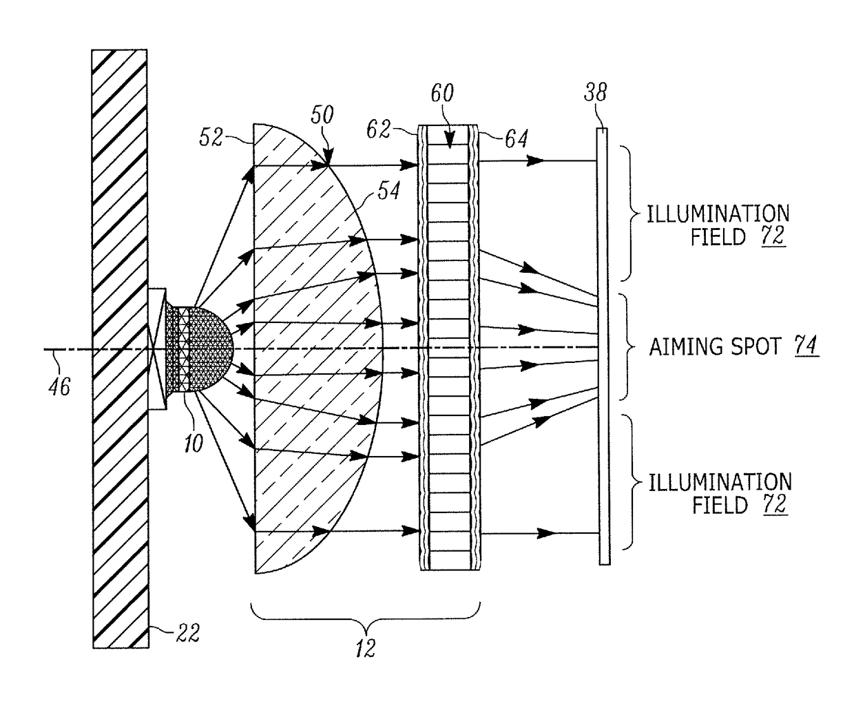
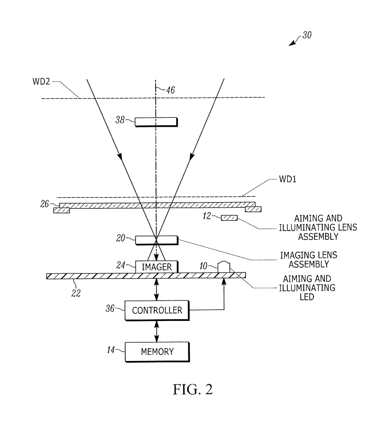
[0016]One aspect of the present disclosure relates to an imaging module for reading a target, e.g., a bar code symbol, to be electro-optically read by image capture. The module includes a hybrid aiming / illuminating light assembly for generating and projecting a visible aiming pattern on the target to locate the target, and for simultaneously generating and projecting an illumination light pattern on the located target to illuminate the located target. The module also includes an imaging assembly for capturing return light over an imaging field of view from the illuminated, located target.

[0017]In a preferred embodiment, the hybrid aiming / illuminating light assembly includes a light source, e.g., a light emitting diode, for emitting visible light rays, a collimating lens component for collimating the light rays, and a lenslet component spaced along an optical axis away from the collimating lens component. The lenslet component has an array of lenslets generally arranged in a plane th...


PUM


Abstract

A hybrid aiming / illuminating light assembly in an imaging reader directs a visible aiming pattern and an illumination light pattern on a target to be read by image capture. In a preferred embodiment, the assembly includes a light source for emitting visible light rays, a collimating lens component for collimating the light rays, and a lenslet component having an array of lenslets configured to optically modify the collimated light rays to generate and project the visible aiming pattern on the target to locate the target, and to also project the illumination light pattern on the target to illuminate the target.

Description

BACKGROUND OF THE INVENTION[0001]The present disclosure relates generally to an imaging module and a system for, and a method of, directing an aiming pattern on, and illuminating, a target to be electro-optically read by image capture during operation of an imaging reader, and more particularly, to a hybrid aiming / illuminating assembly for aiming the reader at, and illuminating, the target during the operation of the reader.[0002]Solid-state imaging systems or imaging readers have been used, in both handheld and / or hands-free modes of operation, to electro-optically read targets, such as one- and two-dimensional bar code symbol targets, and / or non-symbol targets, such as documents. A handheld imaging reader includes a housing having a handle held by an operator, and an imaging module, also known as a scan engine, supported by the housing and aimed by the operator at a target during reading. The imaging module includes a solid-state imager or imaging sensor with an array of photocell...

Claims


Application Information

Patent Timeline
Patent Type & Authority Patents(United States)
IPC IPC(8): G06K7/10G06K7/14G03B15/02
CPCG06K7/10732G06K7/1413G06K2207/1011G02B3/0037G03B15/02G06K7/1417G06K7/146G06K7/10831G06K2007/10524
Inventor BROCK, CHRISTOPHER W.BELISCH, PAUL ANTHONY
Owner SYMBOL TECH LLC
Features
  • R&D
  • Intellectual Property
  • Life Sciences
  • Materials
  • Tech Scout
  • Unparalleled Data Quality
  • Higher Quality Content
  • 60% Fewer Hallucinations
Learn More