Fibrous preforms for use in making composite parts

a technology of fibrous and composite parts, applied in the field of reinforcement, can solve the problems of poor impact resistance of fabricated composite parts, difficult to obtain fiber volume fractions greater than 70% for composite parts, and inability to obtain satisfactory vfr, so as to improve the low-speed impact resistance of obtained composite parts and facilitate parts fabrication

Active Publication Date: 2018-08-28
HEXCEL REINFORCEMENTS SAS
View PDF15 Cites 0 Cited by
  • Summary
  • Abstract
  • Description
  • Claims
  • Application Information

AI Technical Summary

Benefits of technology

[0017]Thus, one of the objectives of the invention is to propose a new intermediate product, adapted to the fabrication of composite parts based on thermosetting resins, and notably by resin injection or infusion, that makes it possible to obtain composite parts with a volume fiber ratio of the order of 60% and with satisfactory mechanical properties, to meet certain very strict specifications, imposed for instance in the field of aviation.
[0018]Another objective of the invention, is to fulfill these specifications, while proposing a symmetrical intermediate product that would be easier to implement and more adapted to automated processes.
[0027]The intermediate material and the process according to the invention make it possible to create composite parts with a VFR of the order of 60%, which corresponds to the standard factor for primary structures in aviation (that is, the vital parts of the aircraft) and also to significantly improve the low-speed impact resistance of the obtained composite parts: for instance, the fall of a tool in a workshop during the fabrication of a composite structure, a collision with a foreign body during its use.
[0028]The pressure applied during an injection process is higher than that used during an infusion process. The result is that it is easier to fabricate parts with a correct VFR, using an injection rather than an infusion process. The materials according to the invention make it possible to reach a desired volume fiber ratio, notably of the order of 60%, even when the composite part is fabricated with a stage c) which uses an infusion rather than an injection of resin. Such an embodiment is also an advantageous variant.

Problems solved by technology

In reality however, it appears difficult to obtain fiber volume fractions greater than 70% for composite parts.
The major drawback of this type of resin is its fragility after polymerizational reticulation, which results in poor impact resistance of the fabricated composite parts.
Document US 2006 / 0154545 describes such a solution in the case of a unidirectional fabric but which given the characteristics of the material described, does not make it possible to obtain a satisfactory VFR.
If the instructions in this document are applied to a layer of carbon fibers with a lesser surface density, 134 g / m2 for instance, the association with a same type of web, but on each side to obtain a symmetric material, would lead to a very low fiber volume ratio, non-compatible with the creation of primary structures for the aeronautic industry.
One of the webs based on a copolyester actually has a negative effect on the impact resistance properties.
At the same time, the lack of precision about the compression alter impact CAI) test (no specification of the impact energy) does not make it possible to deduce the mechanical performances of the indicated measured value.
Consequently, it appears that the addition of a web to the techniques of previous art is carried out most often to the detriment of other mechanical properties.
Indeed, as mentioned earlier, the mechanical properties are primarily determined by the volume fiber ratio (VFR) and the techniques described in previous art do not notably make it possible to obtain composite parts that have a VFR of the order of 60%.

Method used


Image

  • Fibrous preforms for use in making composite parts
  • Fibrous preforms for use in making composite parts
  • Fibrous preforms for use in making composite parts

Examples


example 23

[0140] 4 plies according to example 8—perforation head ø0.8, a photograph of which is shown in FIG. 13

[0141]Example 24: 4 plies according to example 8—perforation head ø0.8, in alternating fashion, a photograph of which is shown in FIG. 14

example 25

[0142] 1 ply according to example 8—perforation head ø1.6, a photograph of which is shown in FIG. 15

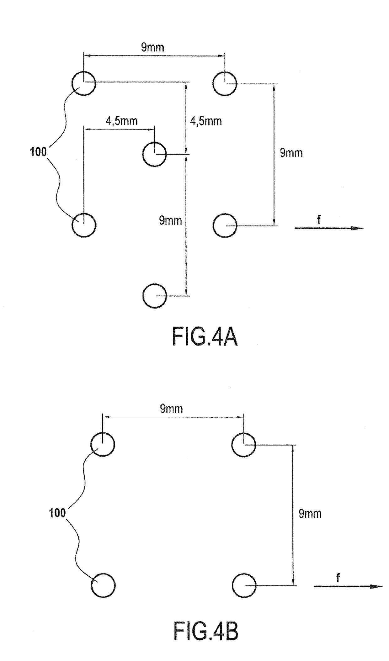
[0143]Example 26: 4 plies according to example 8 welded (without perforation)—The welding uses a head with a diameter of 8 mm heated to a temperature of 200° C., identical to the perforation heads but without the needle. The welds are placed according to FIG. 4a, but spaced by 50 mm. The welds are performed, with a pressure of 30 kPa.

[0144]And as a comparison for the transverse permeability:

[0145]Twill fabric 2. / 2—ref Hexed 48302

[0146]Quasi-isotropic multiaxial 4×194 g / m2 HR stitched with thread 76 dtex−5 mm×5 mm−chain stitch.

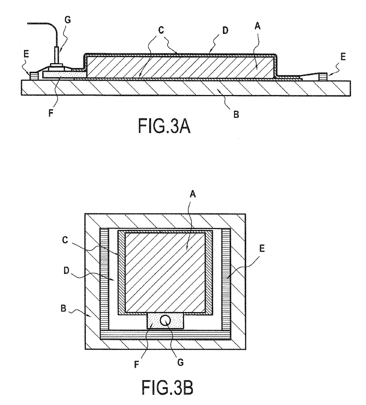
[0147]7. 2 Transverse Permeability Measurements

[0148]The machine and measurement method are described in the thesis entitled “Problems in the measurement of transverse permeability of fibrous preforms for the fabrication of composite structures,” by Romain Nunez, defended at the Ecole Nationale Supérieure des Mines de Saint Etienne, 16 Oct. 2009, The FVR variatio...


PUM

PropertyMeasurementUnit
thicknessaaaaaaaaaa
thicknessaaaaaaaaaa
diametersaaaaaaaaaa

Abstract

The present invention concerns preforms made with a new intermediate material composed of a unidirectional layer of carbon fibers with a weight of 100 to 280 g / m2, associated on each of its faces, with a web of thermoplastic fibers having a thickness of 0.5 to 50 microns, preferably 3 to 35 microns, the intermediate material having a total thickness of 80 to 380 microns, preferably from 90 to 320 microns, and a process for manufacturing composite parts from such preforms and the resulting composite parts.

Description

[0001]This application is a divisional of U.S. Ser. No. 13 / 125,058, filed on Jun. 10, 2011, which is a 371 of PCT / FR09 / 52039, tiled on Oct. 23, 2009.BACKGROUND OF THE INVENTION[0002]1. Field of the Invention[0003]The invention concerns the technical field of reinforcement, materials adapted to the creation of composite parts. More specifically, the invention concerns a new intermediate material containing a unidirectional layer for fabricating composite parts, by subsequent injection or infusion of thermosetting resin, a fabrication process for composite parts from a stack of such a material, as well as the obtained composite parts.[0004]2. Description of Related Art[0005]The manufacture of composite parts or goods, that is, comprising, on one hand, one or more reinforcements or fibrous layers, and on the other hand, a primarily thermosetting (“resin”) matrix and that can include thermoplastics, can for instance, be achieved by a process called “direct” or “LCM” (from the English “L...

Claims


Application Information

Patent Timeline
Patent Type & Authority Patents(United States)
IPC IPC(8): B29C70/08B32B5/02B32B5/22B32B5/26B29C70/54B29B11/12B29B11/16B29C70/22B29C70/44B29K63/00B29K105/08B29K277/00B29K307/04B29L31/30
CPCB29C70/083B29B11/16B29C70/226B29C70/443B29C70/545B29C70/547B32B5/02B32B5/022B32B5/22B32B5/26B29B11/12Y10T428/24975B29K2063/00B29K2105/0881B29K2277/00B29K2307/04B29K2995/0063B29K2995/0089B29K2995/0097B29L2031/3076B32B2260/021B32B2260/04B32B2260/046B32B2262/02B32B2262/0246B32B2262/0253B32B2262/0261B32B2262/0276B32B2262/0292B32B2262/106B32B2307/50B32B2307/558B32B2307/718B32B2605/00B32B2605/18
Inventor BERAUD, JEAN-MARCLAMETHE, JEAN-FLORENTMINNI, JEAN-CHRISTOPHE
Owner HEXCEL REINFORCEMENTS SAS
Why Eureka
Try Eureka