High stability low drag boat hull keel having inverted foil configuration

a low-drag, high-strength technology, applied in the field of boats, can solve the problems of low horsepower motors, narrow bow area, rough ride, etc., and achieve the effect of good fuel economy and maneuverability

Active Publication Date: 2018-08-28
RICKBORN CHRIS
View PDF22 Cites 0 Cited by
  • Summary
  • Abstract
  • Description
  • Claims
  • Application Information

AI Technical Summary

Benefits of technology

[0026]Accordingly, the primary object of the present invention is to provide a boat hull that provides a smooth ride at both high and low speeds with good fuel economy and maneuverability.
[0027]A high and moderate speed boat hull incorporates a keel running the center line of the hull starting 20 to 25% aft of the bow continuing aft 75 to 80% from the bow. The hull has a larger V shaped forward section twisting and flattening out running aft to a much lesser of a V with combinations of flat keel pad and ellipsoidal shaped areas. The keel provides both lift and lessens impact in rough water. The keel has a convex shape vertically and is shallow compared to any other keel. the keel starts thin and is narrow widening aft and tapers gently back to a point with an angel rising aft and up to the hull. This aft shape of the keel directs or allows the water to flow naturally back together over the flat keel pad to create solid water to feed to the engine propeller or propellers. The flat keel pad has two purposes: 1. a dedicated support for the vessel's riding or planning angle. 2. Is it is actually a step and allows the vessel to pivot at high speed and at all speeds giving the vessel greater maneuverability. The V port and starboard of the keel is the area feeding the lifting strakes. The lifting strakes works with the keel to provides positive lift and continues to create the softness of the ride these areas provide. The lifting strakes are shaped in a triangular manner pointing downward and has a radios inside of the lifting strake helping to create the curl of the natural shape of waves both providing lift and softness of the ride in a choppy or rough sea. Outside the lifting stakes continues the genital ellipsoidal shape of the hull and feeds the water out and aft. The spoilers also provide lift both forward in the lager V area and moving aft to the chine flats.
[0028]The spoilers also provide softer looser water or soiled water to the chine flats aft relieving friction of wetted surface of the hull. The chine flatsare wider than most of any hull designs. The chine flats provide stability at rest and on plane at high speed and in a side rougher sea. The chine flats also provide a positive buoyancy giving and assisting the keeland the lifting strakes and the hull a direct attitude from rest to a full plane without squatting, digging or typically raising the bow high out of the water which also allows the vessel to reach a plane and high speed in very shallow water. The chine flat has a step 5 to 10% forward of the transom relieving friction of the wetted surface of the hull. The chine flats are assisted by the bracket or extension which is also a step. The bracket has a large flat bottom angling downward aft of the transom creating more assist in planning as a large trim tab.
[0029]The bracket adds buoyancy to support the weight of engine or engines. The bracket provides positive lift in a following sea lifting up on the inside of the wave and moving the vessel forward decreasing or eliminating the sea engulfing the engine or engines and or sinking the vessel. The bracket's large flat area adds additional stability supporting the chine flats in the side to side motion laying to in large seas preventing violent rocking motion of this vessel, the bracket is also a step allowing this vessel design to pivot over the water aft of the transom and as the bracket dose not touch the water at speed or plane it does not create drag at speed.

Problems solved by technology

Characteristically, however, the flat, broad bow area creates a rough ride.
These boats are usually limited to low horsepower motors because they do not generally handle well at high speed.
“Displacement” hulls push through or cruise through the water instead of skimming on the surface and are not able to operate at the higher speeds of a planing hull.
At slow speeds they are more efficient than Planing hulls but not as efficient as Displacement hulls, while at medium speed they are more efficient than both Displacement and Planing hulls.
Semi Displacement hulls are not usually able to operate at the high speeds typical of Planing hulls but are able to operate efficiently at higher speeds than a Displacement hull.
However, at low speed a deep V hull is very inefficient.
Furthermore, at low speeds, a deep V hull is less stable, less maneuverable and tends to roll side to side to a high degree when side on to the waves.
However, these keels also resulted in slowness in stays, excess wetted surface and an inefficient lateral plane shape that has excess leeway.

Method used


Image

  • High stability low drag boat hull keel having inverted foil configuration
  • High stability low drag boat hull keel having inverted foil configuration
  • High stability low drag boat hull keel having inverted foil configuration

Examples


Embodiment Construction

[0057]Before explaining at least one embodiment of the invention in detail, it is to be understood that the invention is not limited in its application to the details of construction and to the arrangements of the components set forth in the following description or illustrated in the drawings. The invention is capable of other embodiments and of being practiced and carried out in various ways. Also, it is to be understood that the phraseology and terminology employed herein are for the purpose of description and should not be regarded as limiting.

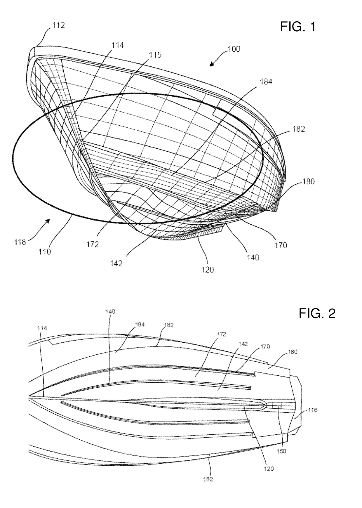
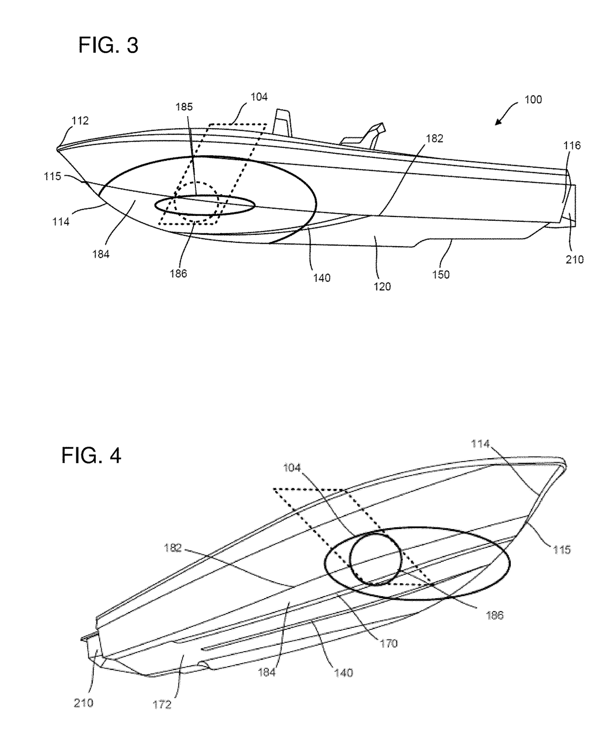
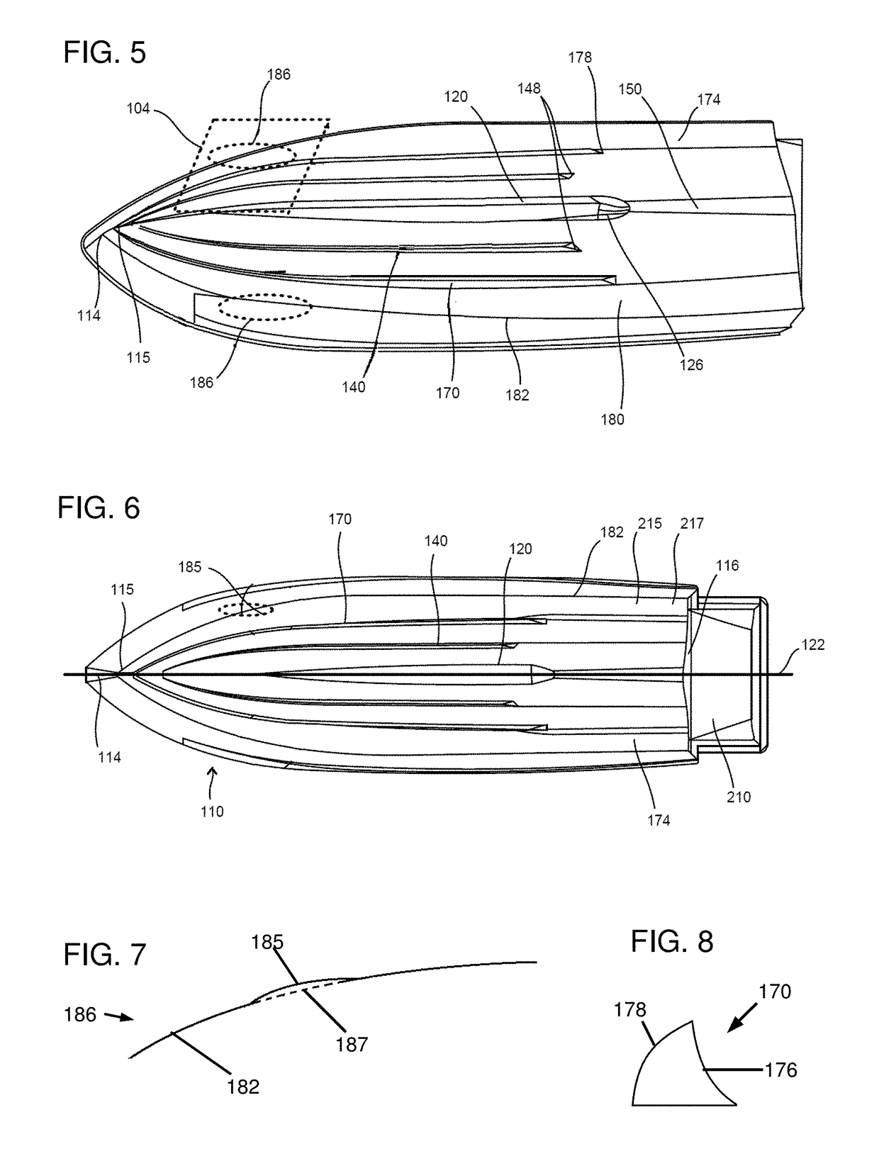
[0058]Disclosed is a hull design that improves the stability of a boat at low speed and efficiency at high speed. The forward region of the hull may have a bulbous, i.e. ellipsiodal, area that may be centered around the chine within the impact zone of the boat. The impact zone is the area or region of the hull impacted by water projecting upward due to the hull moving through water and is generally in a region extending from about 15% to a...


PUM

PropertyMeasurementUnit
dead rise angleaaaaaaaaaa
aspect ratioaaaaaaaaaa

Abstract

A modified V-hull boat has a keel having a horizontal cross-sectional profile of an inverted foil. The leading edge of the keel is a sharp point and the front region of the keel tapers outward along the length of the keel until it reaches its widest point. The widest point is aligned with the center of gravity of the hull. The trailing edge is a rounded blunt edge. The aft region of the keel is substantially shorter in length than the front region of the keel.

Description

CROSS-REFERENCE TO RELATED APPLICATIONS:[0001]This application is a continuation-in-part of U.S. Pat. No. 9,284,019 filed on May 16, 2014 and issued on Mar. 15, 2016, is a continuation-in-part of U.S. patent application Ser. No. 15 / 071,007 filed on Mar. 15, 2016, and claims priority to U.S. Provisional Application Ser. No. 61 / 824,339 filed on May 16, 2013, the contents of which are hereby incorporated in their entirety.STATEMENT REGARDING FEDERALLY SPONSORED RESEARCH OR DEVELOPMENT[0002]Not Applicable.NAMES OF PARTIES TO A JOINT RESEARCH AGREEMENT[0003]Not ApplicableREFERENCE TO SEQUENCE LISTING, A TABLE, OR A COMPUTER PROGRAM LISTING APPENDIX SUBMITTED ON A COMPACT DISC AND INCORPORATION-BY-REFERENCE OF THE MATERIAL[0004]Not Applicable.COPYRIGHT NOTICE[0005]A portion of the disclosure of this patent document contains material which is subject to copyright protection. The copyright owner has no objection to the facsimile reproduction by anyone of the patent document or the patent di...

Claims


Application Information

Patent Timeline
Patent Type & Authority Patents(United States)
IPC IPC(8): B63B3/38B63B1/04B63B1/20B63B5/24B63B3/14
CPCB63B3/38B63B1/042B63B3/14B63B5/24B63B1/20B63B2001/201
Inventor RICKBORN, CHRIS
Owner RICKBORN CHRIS
Why Eureka
Try Eureka