Protective garments

a technology of composite fabrics and protective garments, applied in the direction of protective garments, other domestic objects, protective equipment, etc., can solve the problems of ineffective knife or needle threat, inconvenient use, and average resistance of materials to cut and slash attacks, etc., and achieve the effect of cost-effectiveness

Active Publication Date: 2018-08-28
PREMIUM SECURITY AS
View PDF21 Cites 1 Cited by
  • Summary
  • Abstract
  • Description
  • Claims
  • Application Information

AI Technical Summary

Benefits of technology

[0016]The potential effectiveness of such combinations may be illustrated by the example in which the fibers of the textile layer are para-aramid fibers. When such a textile layer was placed in proximity to a layer of stainless steel mesh, it was found to produce a composite material having the surprising property of a puncture resistance that is 30%-40% greater than that expected from a linear combination of the cut and puncture resistance properties of each individual layer, while maintaining the combined ballistic and needle protection of each layer. Combining fabric layers made of other well-known fabric fibers may, therefore, produce similarly surprisingly enhanced combined protective properties.
[0022]It is an object of the present invention to provide improved wearable protective garments capable of a combination of properties such as high level ballistic, cut and slash, puncture and needle protection and heat protection.
[0023]It is another object of the present invention to provide cost effective, lightweight materials for protective garments.

Problems solved by technology

The materials are, however, only of average resistance to cut and slash attacks and to puncture by needles.
The garments constructed from such materials, such as, but not limited to, para-aramid based body armor, therefore, provide good protection against gun attacks, but are not particularly effective against knife or needle threats.

Method used


Image

  • Protective garments
  • Protective garments
  • Protective garments

Examples


Embodiment Construction

[0041]The preferred embodiments of the present invention will now be described in more detail with reference to the drawings in which identical elements in the various figures are, as far as possible, identified with the same reference numerals. These embodiments are provided by way of explanation of the present invention, which is not, however, intended to be limited thereto. Those of ordinary skill in the art may appreciate upon reading the present specification and viewing the present drawings that various modifications and variations may be made thereto.

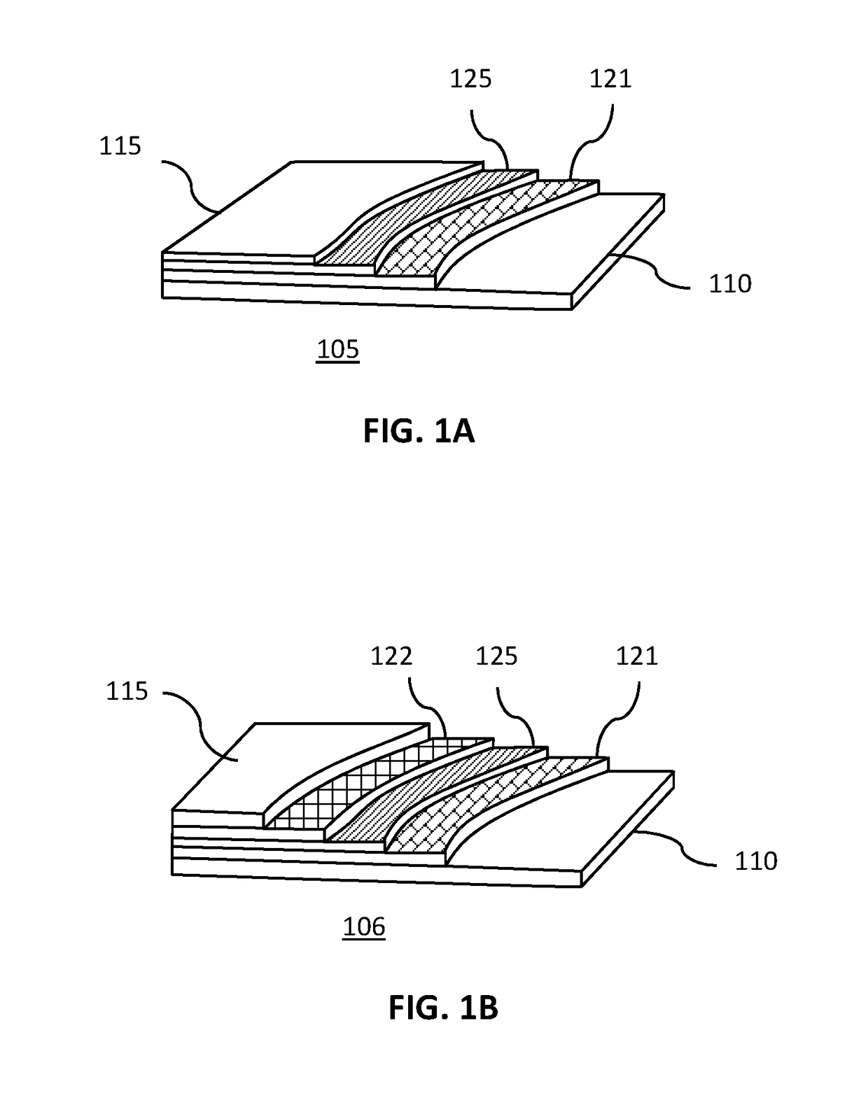
[0042]FIG. 1 shows a schematic cut-away isometric view of the layers of a protective, composite fabric 105 of one embodiment of the present invention.

[0043]The protective, composite fabric 105 may, for instance, have a first-textile layer 121 adjacent to a metal mesh layer 125 with both layers sandwiched between an outer protective layer 115 and an inner protective layer 110. The inner and outer protective layers may be any fabri...


PUM

PropertyMeasurementUnit
diameteraaaaaaaaaa
diameteraaaaaaaaaa
thicknessaaaaaaaaaa

Abstract

Garments made from a composite, protective fabric are disclosed. The composite fabric has textile layers placed in proximity to metallic mesh layers of woven stainless steel mesh. The metal mesh layers formed from any metal which forms suitable fibers. The textile layers are fabric formed with well-known fabric fibers selected from those including para-aramid fibers, meta-aramid fibers, ultra-high molecular weight polyethylene fibers, polyethylene terephthalate fibers, cellulose fibers, polyamide fibers, a mixture of para-aramid fibers and meta-aramid fibers, and a mixture of para-aramid fibers and carbon fibers. Forming the non-metal textile layers is by any suitable method for interlacing yarns including weaving, knitting, crocheting, knotting, or felting, or combinations thereof. The garments made using the fabric include gloves, bullet proof vests and chain-saw resistant trousers.

Description

CROSS-REFERENCE TO RELATED APPLICATIONS[0001]This application is a Continuation-in-Part of U.S. patent application Ser. No. 15 / 454,834 entitled “Protective Garments” filed on Mar. 9, 2017, which in turn is a Continuation-in-Part of US patent application Ser. No. 14 / 992,829 entitled “Composite, Protective Fabric and Garments made thereof” file on Jan. 11, 2016, which in turn is a Continuation-in-Part of U.S. patent application Ser. No. 14 / 791,059 entitled “Stretchable Metal Mesh Protective Material and Garments” filed on 2 Jul. 2015, the contents of all of which are hereby fully incorporated by reference in their entirety.BACKGROUND OF THE INVENTION[0002](1) Field of the Invention[0003]The invention relates to garments made from a composite fabric having superior cut and puncture resistance, and more particularly to garments made from a fabric having a combination of layers of metal mesh and textile layers of woven, non-metallic fibers, the non-metallic fibers including ones selected...

Claims


Application Information

Patent Timeline
Patent Type & Authority Patents(United States)
IPC IPC(8): A41D1/04F41H1/08A41D13/018B32B25/14B32B25/10B32B5/02B32B5/26F41H1/02A41D19/00A42B3/06F41H5/04A41D19/015A41D1/06A41D31/00A41D13/06A41D3/00A43B7/32
CPCF41H5/0464A41D1/06A41D3/00A41D13/018A41D13/065A41D19/0006A41D19/01511A41D19/01523A41D31/005A41D31/0061A42B3/063A43B7/32B32B5/024B32B5/028B32B5/26B32B25/10B32B25/14F41H1/02F41H1/08A41D1/04B32B2571/02A41D2500/10A41D2500/20A41D2500/52B32B2262/0253B32B2262/0276B32B2262/103B32B2307/56B32B2307/581A41D13/015A41D31/285A41D31/245
Inventor ANDRESEN, LARS PETTER
Owner PREMIUM SECURITY AS
Why Eureka
Try Eureka