Eureka AIR delivers breakthrough ideas for toughest innovation challenges, trusted by R&D personnel around the world.

Method, apparatus, and article for frequency-overlapped 3-D multispectral magnetic resonance images

a frequency-overlapped, multi-spectral technology, applied in the field of magnetic resonance imaging, can solve the problems of insufficient tr of 3d multispectral protocols with tr sufficiently short to generate t1 contrast images, and achieve the effect of enhancing t1 contrast without detracting from image clarity

Active Publication Date: 2018-08-28
GENERAL ELECTRIC CO
View PDF8 Cites 4 Cited by
  • Summary
  • Abstract
  • Description
  • Claims
  • Application Information

AI Technical Summary

Benefits of technology

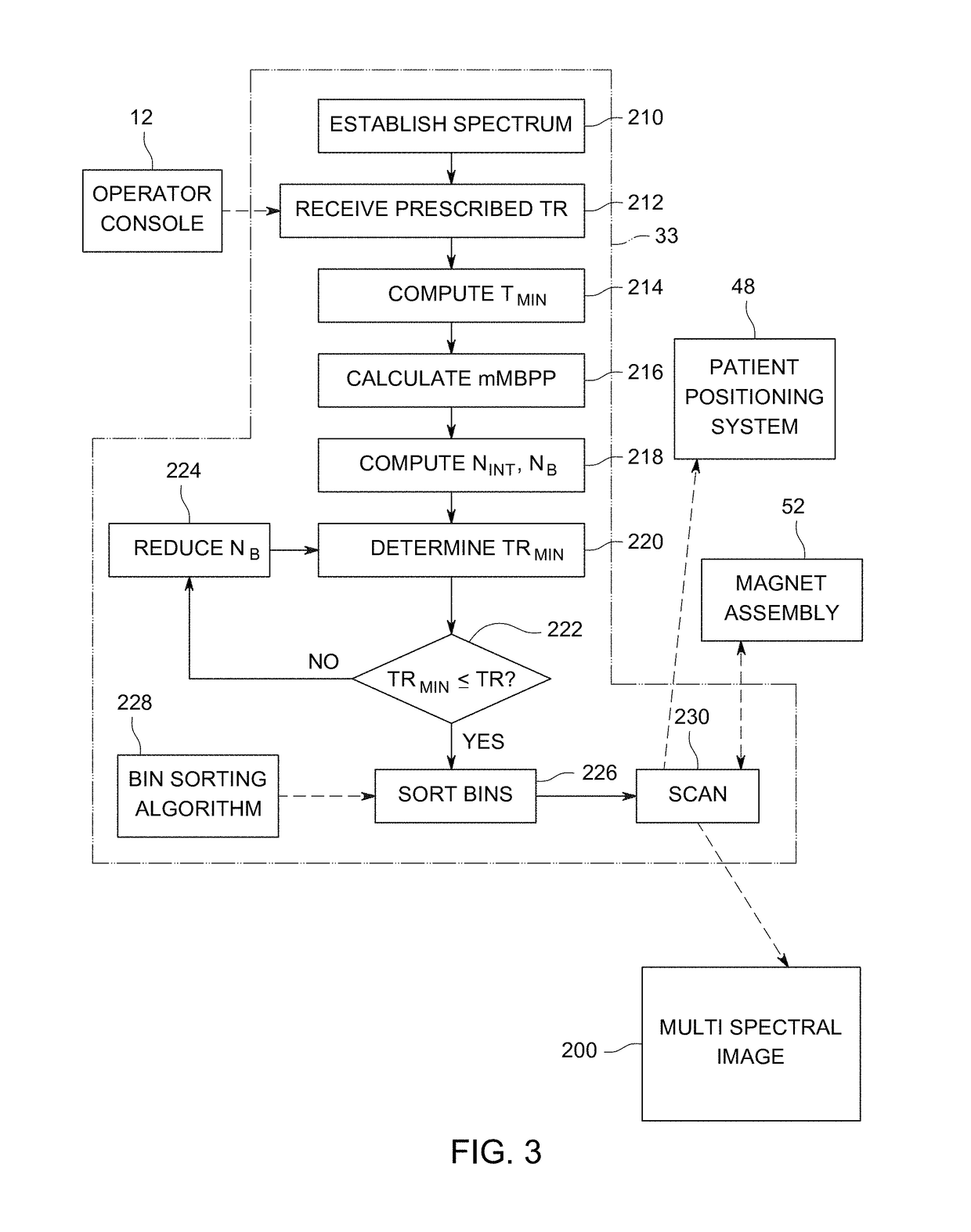
[0004]In view of the above, it is desirable to provide 3-D multispectral MRI in which scan intervals are automatically scheduled to allow for flexible repetition times and therefore enhance T1 contrast without detracting from image clarity.

Problems solved by technology

Minimum sequence repetition times (TR) of such overlapping 3D multispectral protocols have been limited, due to a need for careful management of spectral window crosstalk within interleaved acquisition sections.
Accordingly, 3D multispectral protocols have not been used with TR sufficiently short to generate T1 contrast images.

Method used


Image

  • Method, apparatus, and article for frequency-overlapped 3-D multispectral magnetic resonance images
  • Method, apparatus, and article for frequency-overlapped 3-D multispectral magnetic resonance images
  • Method, apparatus, and article for frequency-overlapped 3-D multispectral magnetic resonance images

Examples


Embodiment Construction

[0016]Reference will be made below in detail to exemplary embodiments of the invention, examples of which are illustrated in the accompanying drawings. Wherever possible, the same reference characters used throughout the drawings refer to the same or like parts, without duplicative description. Exemplary embodiments of the present invention are described with respect to 3D multispectral magnetic resonance imaging (3D MS MRI).

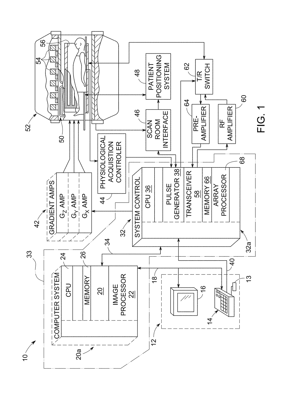
[0017]FIG. 1 depicts major components of an exemplary magnetic resonance imaging (MRI) system 10 that incorporates embodiments of the present invention. The operation of the system is controlled from an operator console 12, which includes a keyboard or other input device 13, a control panel 14, and a display screen 16. The input device 13 can include a mouse, joystick, keyboard, track ball, touch activated screen, light wand, voice control, or any similar or equivalent input device, and may be used for interactive geometry prescription. The console 12 communicat...


PUM


Abstract

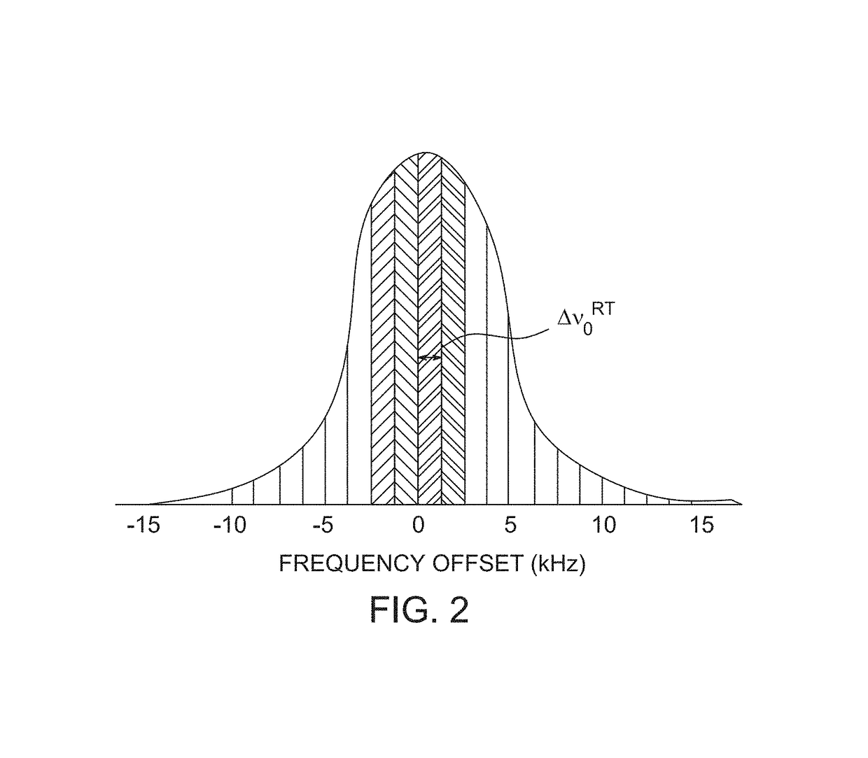
A method for acquiring 3D multispectral MRI of a target includes scanning a spectrum of spectral windows with an MRI scanner, wherein each spectral window of the spectrum defines a continuously-differentiable distribution of frequencies around a scan frequency and adjacent scan frequencies are spaced apart by substantially uniform frequency offsets such that adjacent spectral windows substantially uniformly overlap, wherein selected adjacent spectral windows are scanned in consecutive passes, and nearest neighbor spectral windows within each pass are scanned at a maximum temporal spacing within the pass.

Description

BACKGROUNDTechnical Field[0001]Embodiments of the invention relate generally to methods for magnetic resonance imaging (“MRI”). Particular embodiments relate to methods for enhancement of MRI in inhomogeneous magnetic fields, e.g., for patients having paramagnetic implants such as joint replacements.Discussion of Art[0002]In MRI imaging, when human or other animal tissue is subjected to a uniform magnetic field, i.e., a polarizing field B0, the individual magnetic moments of particle spins in the tissue attempt to align with the polarizing field, but precess about the field in random order at their characteristic Larmor frequency. If the tissue is subjected to an RF magnetic field, i.e., excitation field B1, which defines an x-y plane and varies at a frequency near a Larmor frequency of selected particles, the net aligned moment, or “longitudinal magnetization” of those selected particles, may be rotated, or “tipped”, into the x-y plane to produce a net transverse magnetic moment. A...

Claims


Application Information

Patent Timeline
Patent Type & Authority Patents(United States)
IPC IPC(8): G01V3/00G01R33/565G01R33/561
CPCG01R33/56536G01R33/5617
Inventor GUI, DAWEIKOCH, KEVIN MATTHEW
Owner GENERAL ELECTRIC CO
Why Eureka
Eureka Blog
Learn More