
Method for monitoring a process and/or production plant

a technology for production plants and processes, applied in the direction of program control, total factory control, instruments, etc., can solve the problems of inconsistentness, condition of data, and safeguarding currentness, so as to facilitate the monitoring of process and/or production plants, the effect of improving efficiency

Active Publication Date: 2018-08-28
SIEMENS AG
View PDF5 Cites 0 Cited by
  • Summary
  • Abstract
  • Description
  • Claims
  • Application Information

AI Technical Summary

Benefits of technology

The present invention aims to provide an efficient way to monitor and analyze processes and production plants. This is achieved by extracting topology data from the output of engineering systems and operating data from the components of the plant. These data are used to create a model or map of the plant that can be correlated with the current process data. This model can aid in optimizing operations management and advancing the development of applications without giving up their autonomy. The topology data can be the input-side or output-side operative connection of components, which simplifies the sensing of connections between components in the plant. This model can also be adjusted in response to changes in result data, allowing for the integration of data from different applications or trades without the need for complete re-implementations.

Problems solved by technology

Hence, not only the conditioning of the data but also, in particular, the safeguarding of the currentness (e.g., the up-to-date state) and consistency are a problem, since there are no standard mechanisms available therefor.
Not only is there a lack of products on the market that can be used to manage the results and to keep them up to date from an engineering process, there is even a lack of design principles therefor.
This problem arises particularly for the activities related to operations management phase, i.e., service and maintenance activities, but also for cause analysis.
This currently requires the topology to be stored in the form of programs, which results in the programs needing to be analyzed and revised in the event of changes in the plant.
There is therefore no application-spanning or trade-spanning model available.
In addition, the topology cannot be derived from these data and documents.
The topology of a plant likewise cannot be evaluated automatically for a DMS system, however.
There are ways of transferring this method to plant construction, e.g., delivering the engineering systems and data to the operator of the plant and involving them in the operations management, which is not possible with a PDM system, for example.
A disadvantage of the approach is that such an engineering tool cannot be optimized for the operations management and for the engineering in equal measure.
Data from extraneous systems need to be imported manually and adapted to the data model, which makes currentness (i.e., up-to-date state) and consistency maintenance difficult.
A further problem is the need for various statements of task in plant construction to be implemented by such a tool.
As a rule, this is a very expensive and risky path, since heterogeneous engineering systems need to be put onto a common platform with their complete scope of functions, which has usually come into being over years.
In the past, multiple instances of such developments have failed, since the term of the development project means that they have likewise had to functionally expand the existing engineering systems for customers, and hence the implementation of the new system has become ever more difficult and more expensive.
In many cases, such platform approaches are also no longer “best of breed”, and a succession of customers also does not wish to make itself dependent on one supplier alone.
In this case too, many efforts have been stranded, not least because the manufacturers of engineering tools do not wish their engineering tools to be interchangeable.

Method used


Image

  • Method for monitoring a process and/or production plant
  • Method for monitoring a process and/or production plant

Examples


Embodiment Construction

[0034]The embodiments outlined in more detail below are preferred embodiments of the present invention.

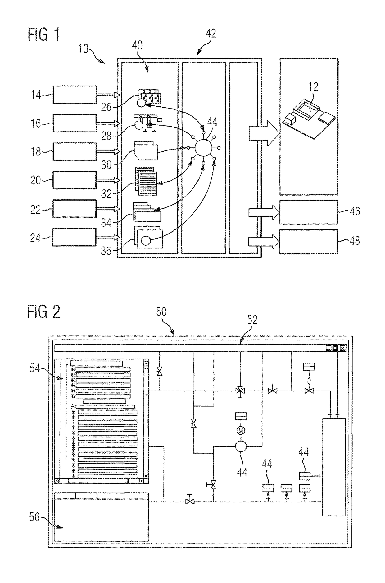
[0035]FIG. 1 shows a schematic illustration of an apparatus 10 for checking a process and / or production plant 12 in accordance with one embodiment of the present invention. The process and / or production plant 12 is planned using a plurality of engineering systems. In the present case, the plant 12 is planned using six engineering systems 14, 16, 18, 20, 22, and 24. The engineering systems 14, 16, 18, 20, 22, 24 relate to different technical areas. By way of example, engineering system 14 can be used to provide a pipeline and installation plant. The engineering system 16 can be used to provide a schematic diagram. The engineering system 18 can be used to provide a three-dimensional plan of the plant 12. The engineering system 20 can be used to provide data sheets pertaining to the components 44 of the plant 12. The engineering system 22 can be used to provide continuous function cha...


PUM


Abstract

A method for monitoring a process and / or production plant, which includes a plurality of components and which is planned using a plurality of engineering systems, includes a step of providing first result data pertaining to at least one portion of the plurality of components using a first of the plurality of engineering systems, and second result data pertaining to at least one portion of the plurality of components using a second of the plurality of engineering systems. The method also includes a step of extracting topology data, which describe an arrangement of the plurality of components within the process and / or automation plant, and operating data for the plurality of components from the first and second result data. The method further includes creating a model for the process and / or production plant by using the topology data and the operating data. Also disclosed is an apparatus for carrying out the method.

Description

FIELD OF THE INVENTION[0001]The present invention relates to a method and apparatus for monitoring a process and / or production plant that comprises a plurality of components and that is planned using a plurality of engineering systems. In addition, the present invention relates to an apparatus for monitoring a process and / or production plant.DESCRIPTION OF THE RELATED ART[0002]There are currently considerable shortcomings in conditioning information about a plant in a system-spanning manner. Electronically evaluable “as-built” plant documentation that is present in a standard form can still be obtained only in exceptional cases. This applies particularly when suppliers are involved, e.g., in distribution or in transport engineering. On account of the heterogeneity of the system landscape in engineering, the documents, data and programs they produce cannot be correlated in automated fashion today—this needs to be performed manually with a high level of involvement. Hence, not only th...

Claims


Application Information

Patent Timeline
Patent Type & Authority Patents(United States)
IPC IPC(8): G06G7/48G06F17/50G05B19/418G06Q10/06G05B17/02
CPCG06F17/5009G05B19/4188G05B19/41885G06Q10/06Y02P90/26G05B2219/31393G05B2219/31398Y02P90/20Y02P90/24G05B17/02Y02P90/02G06F30/20
Inventor DALLMANN, MICHAELELGER, JURGENGAST, CHRISTIANEREMMEL, MARKUSTRENNER, THOMAS
Owner SIEMENS AG
Learn More