Method and apparatus for operating a screening wheel filter

Active Publication Date: 2018-09-04
GNEUSS GMBH
View PDF17 Cites 0 Cited by
  • Summary
  • Abstract
  • Description
  • Claims
  • Application Information

AI Technical Summary

Benefits of technology

The patent aims to improve the cleaning of mesh inserts in a way that saves more cleaning agent, achieves better cleaning results, and reduces energy usage.

Problems solved by technology

In this regard, it is disadvantageous that, given the required size of the back-flush nozzle, large quantities of cleaning agents are required in order to saturate the mesh insert over the required width with the cleaning agents.
Particularly at edges of the mesh inserts, insufficient cleaning often occurs because the melt pressure of the back-flushing station is often no longer sufficient there.
Effective, melt-saving cleaning is not possible.
Here, too, no actively functioning cleaning-agent supply is provided.
As a result of the continuous cleaning process, an especially large amount of the cleaning agent, i.e. the melt, is wasted.

Method used


Image

  • Method and apparatus for operating a screening wheel filter
  • Method and apparatus for operating a screening wheel filter

Examples


Embodiment Construction

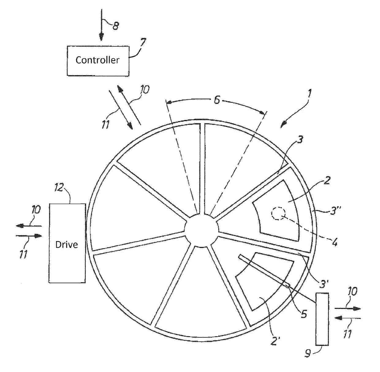
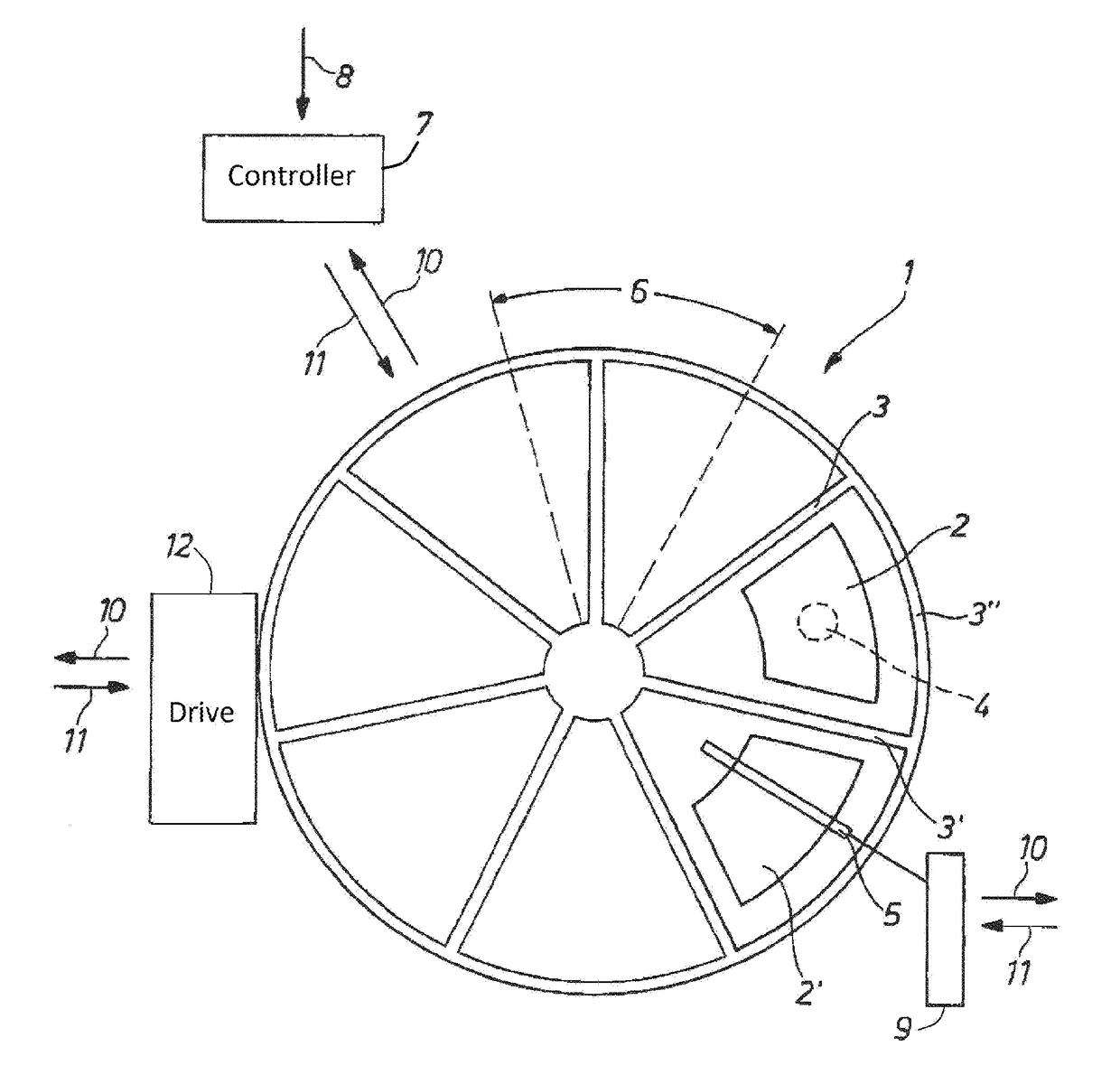
[0026]The FIGURE is a schematic view of a sieve wheel 1 in which two mesh inserts 2 and 2′ are shown to represent a large number of mesh inserts. The mesh inserts 2 are set between bars 3, 3′, 3″ resting against the inner wall of a sieve-wheel filter housing. The mesh insert 2 is aligned with a melt conduit 4, and the mesh insert 2′ is aligned with a cleaning slot 5 of the back-flushing station. It can clearly be seen that the cleaning slot 5 has a substantially greater radial length than the mesh insert 2′ but a substantially smaller angular width perpendicular to the radial direction than the mesh insert 2′ and than an angular travel 6 per rotational step.

[0027]A controller 7 working with or without feedback has an input 8 for loading parameters and on the other hand receives via a data connection 10 input such as differential pressure, rotational speed, charge state of the cleaning-agent supply 9, etc. The controller 7 can influence the rotary drive 12 and / or the cleaning-agent s...


PUM

PropertyMeasurementUnit
Temperatureaaaaaaaaaa
Lengthaaaaaaaaaa
Fractionaaaaaaaaaa

Abstract

A method and an apparatus for operating a screening wheel filter for high-viscosity melts with pressures of >10 bar and temperatures of >90° C., wherein a screening wheel (1) is rotationally driven step by step, and screening inserts (2) arranged in the screening wheel (1) are successively subjected to a stream of cleaning agent produced by a cleaning agent drive (9) in a backflushing cleaning station, are to be optimized in such a way that less cleaning agent is used, better cleaning of the screening inserts takes place and a saving of energy is ensured. For this purpose it is proposed that the cleaning backflushing in the backflushing cleaning station takes place during the rotation of the screening wheel (1), wherein an open-loop or closed-loop control device (7) assigned to the cleaning agent drive (9) is used to set the amount of cleaning agent and / or the pressure of the cleaning agent and / or the flow rate of the cleaning agent in dependence on the rotational speed of the screening wheel (1) and / or in dependence on a differential pressure prevailing at the screening inserts (2) located in the melt channel (4) and the effective opening of the slot die normal to the radial is less than the distance covered by the screening wheel (1) during a driving step.

Description

CROSS REFERENCE TO RELATED APPLICATIONS[0001]This application is the US-national stage of PCT application PCT / EP2014 / 059088 filed 5 May 2014 and claiming the priority of German patent application 102013208637.7 itself filed 10 May 2013.FIELD OF THE INVENTION[0002]The invention relates to a method of operating a sieve-wheel filter for high-viscosity melts with pressures of >10 bar and temperatures of >90° C., the sieve wheel being rotated in steps and mesh inserts arranged in the sieve wheel in a back-flushing station being successively traversed by a stream of cleaning agent generated by a cleaning-agent supply, as well as to a sieve-wheel filter for executing the method.BACKGROUND OF THE INVENTION[0003]Sieve-wheel filters with a corresponding back-flushing station belong to the prior art as presented, for example, by DE 103 26 487 [U.S. Pat. No. 7,411,163]. In such sieve-wheel filters, mesh inserts located in the melt conduit are rotated away from the melt conduit via a drive...

Claims


Application Information

Patent Timeline
IPC IPC(8): B29C47/08B29C47/92B29C47/68B29C48/92
CPCB29C47/0886B29C47/683B29C47/92B29C2947/92961B29C2947/9259B29C2947/9299B29C2947/92514B29C47/0884B29C48/273B29C48/92B29C48/6914B29C48/2725B29C2948/9259B29C2948/9299B29C2948/92514B29C2948/92961B29B7/58
Inventor GNEUSS, DETLEFGNEUSS, STEPHANGNEUSS, DANIEL
Owner GNEUSS GMBH
Why Eureka
Try Eureka