
Industrial electric dust removing device purifying system

A purification system and industrial electricity technology, applied in the direction of external electrostatic separator, power supply technology, electrostatic separation, etc., can solve the problem that the purification effect cannot meet the requirements, and achieve the effect of good dust removal effect, low operating cost and low price.

Active Publication Date: 2006-12-27
高国纯
View PDF0 Cites 0 Cited by
  • Summary
  • Abstract
  • Description
  • Claims
  • Application Information

AI Technical Summary

Problems solved by technology

[0002] High-voltage electrostatic precipitators are widely used in metallurgy, building materials, chemical industry, papermaking and other fields to protect the environment and recycle resources. Currently, the electrostatic precipitators that have been in operation, due to the defects in the control of process conditions, especially in asphalt smoke and In the application of gas purification, the purification effect cannot meet the requirements

Method used


Image

  • Industrial electric dust removing device purifying system
  • Industrial electric dust removing device purifying system
  • Industrial electric dust removing device purifying system

Examples


Embodiment 1

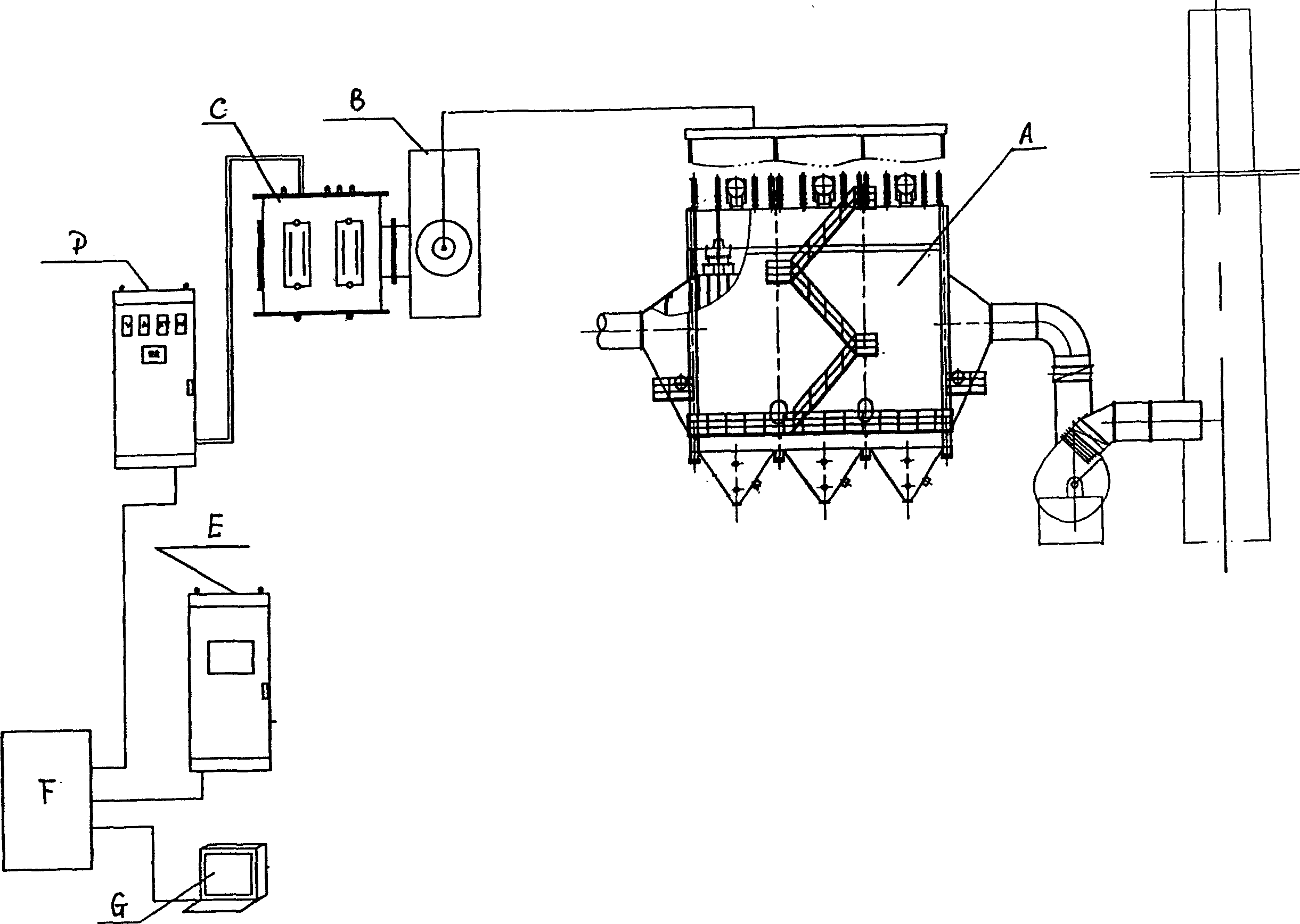
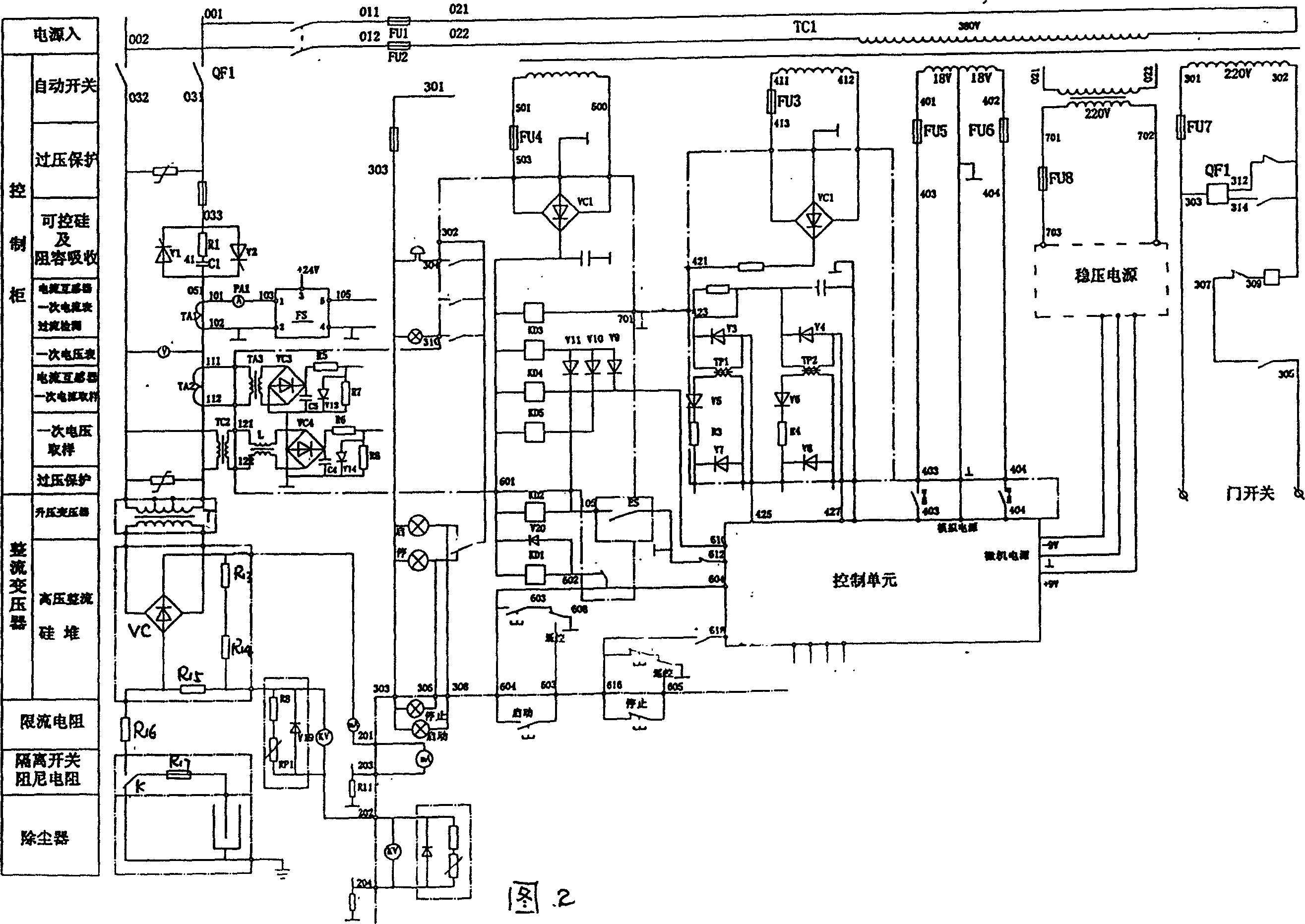
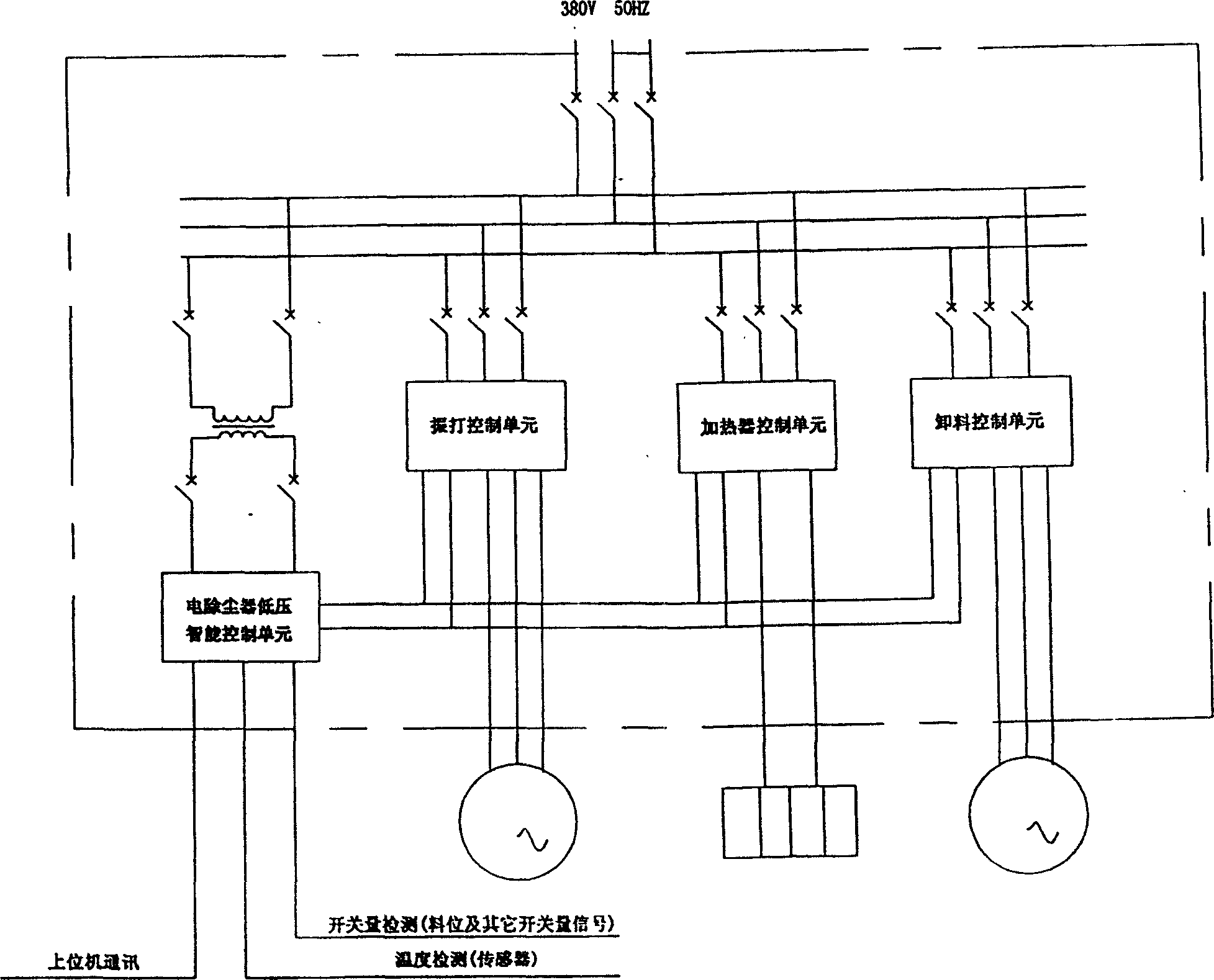
[0023] figure 1 ,figure 2, image 3 The specific description with reference to the accompanying drawings has been described in detail in the previous technical solutions.

[0024] See Figure 4 , the structural structure of the electromagnetic rapper on the top of the dust collector is: the rapping hammer 2 is set inside the insulating cylinder 1, the lower part of the rapping hammer 2 is a rapping rod 8, and the outer part of the rapping rod 8 is provided with a gasket 9; 1 There is a coil 3 on the outside, the outside of the coil 3 is the shell 4, and the outside of the shell is provided with a junction box 5, which is used to energize the coil, an insulating seal 6 is provided at the bottom of the coil 3, and the dust collector top plate 10 is at the bottom of the vibrator. There is a flange connection 7 outside the rapping rod and the rapping hammer.

[0025] Figure 5 It is the microcomputer control schematic diagram of electromagnetic rapping. The rectification devic...

Embodiment 2

[0029] See Image 6 , when dealing with asphalt fume, the dust collector 11 ( figure 1 Middle A) A spray cooler 12 is provided at the front end, a diffuser 13 is provided at the front of the spray cooler 12, a smoke separator 14 is provided at the front of the diffuser 13, and an asphalt filter is provided at the front of the smoke separator 14. Special electric butterfly valve 16.

[0030] As shown in Figure 7, the lower part of the spray cooler is provided with a drain pipe 17, a cleaning pipe 18, a water inlet pipe 19, and a spraying device 20, and an air distribution plate 21 is provided at the entrance of the spray cooler, and an airflow distribution plate 21 is provided at the entrance of the spray cooler. Air intake pipe 22 is arranged, and manhole 23 and temperature measuring connector 24 are also arranged on cooler.

[0031] As shown in Fig. 8 and Fig. 9, a frame 26 and an ash hopper 25 are provided at the bottom of the smoke separator, a side wall plate 30 is provi...


PUM


Abstract

The present invention relates to industrial electrically dusting purification system comprising electric duster, high voltage DC power supply and low voltage PLC control system. The purification system is provided with high voltage SCR power supply, upper computer communication interface for communication with upper computer, and low voltage control system with programmable PLC controller to control the pulse shaker, heater and discharge unit of the electric duster. The present invention adopts live showing clean technology to spray atomized water to clean dust collecting electrode and discharge electrode for optimized electric field cleaning effect and lowered operation cost; and has also electromagnetic shaker. The present invention has reasonable structure, high dusting effect and low cost.

Description

technical field [0001] The invention relates to an industrial electric precipitator purification system composed of an electric precipitator and its high-voltage DC power supply device and a PLC low-voltage control system. Background technique [0002] High-voltage electrostatic precipitators are widely used in metallurgy, building materials, chemical industry, papermaking and other fields to protect the environment and recycle resources. Currently, the electrostatic precipitators that have been in operation, due to the defects in the control of process conditions, especially in asphalt smoke and In the application of gas purification, the purification effect cannot meet the requirements. Utility model content [0003] The purpose of the present invention is to provide a self-developed industrial electric precipitator purification system that overcomes the shortcomings of the prior art. [0004] Industrial electric precipitator purification system is characterized in that...

Claims


Application Information

Patent Timeline
Patent Type & Authority Patents(China)
IPC IPC(8): B03C3/68B03C3/16B03C3/76B03C3/66B03C3/78
Inventor 高国纯陈雁费丽英王兆东李轶
Owner 高国纯
Learn More