
Tethered unmanned aerial vehicle

a technology of unmanned aerial vehicles and tethered vehicles, which is applied in the field of tethered, unmanned aerial vehicles, can solve the problems of high mission cost of operating a uav, limited payload capacity of many uavs, and difficulty in deploying and deploying. achieves the effect of easy deployment and very long flight duration

Active Publication Date: 2018-09-04
HARRIS CORP
View PDF10 Cites 11 Cited by
  • Summary
  • Abstract
  • Description
  • Claims
  • Application Information

AI Technical Summary

Benefits of technology

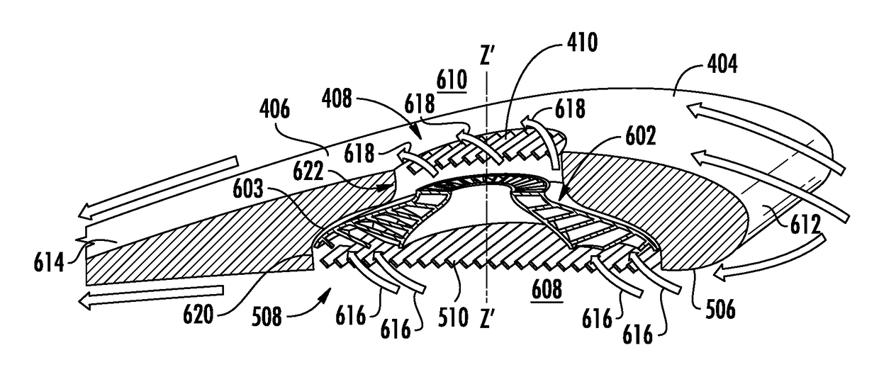
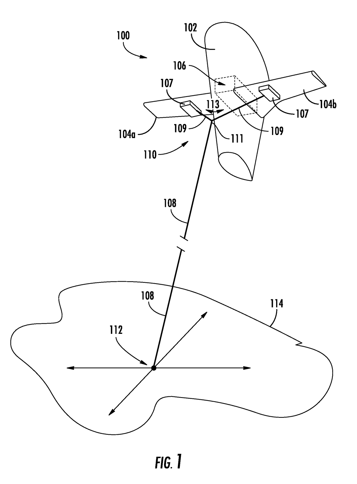
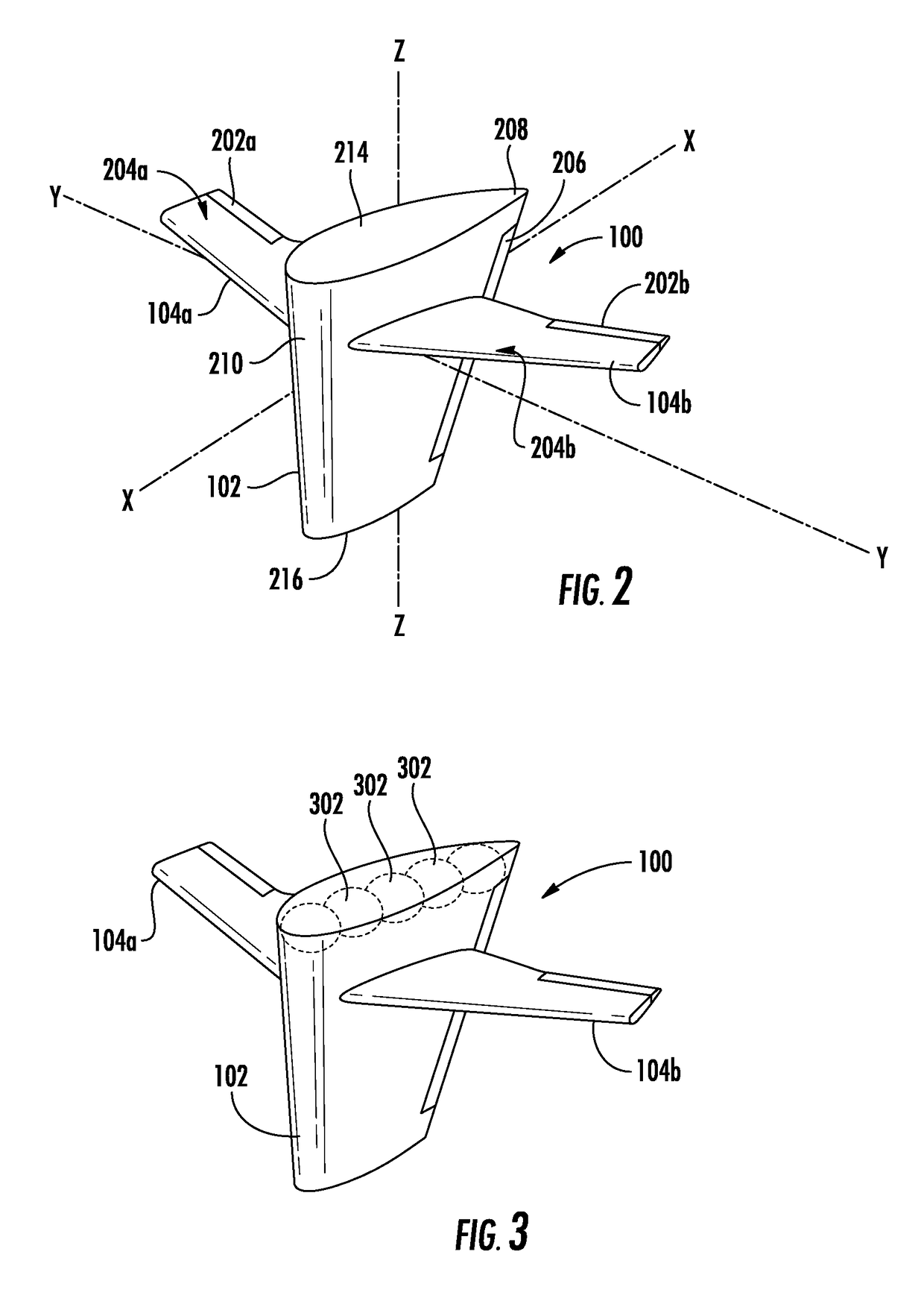
[0007]According to a further aspect, there is disclosed herein a method for providing an airborne platform which is easily deployed and capable of very long duration flights without human intervention. The method involves maintaining a (TUAV) aloft using at least one buoyancy cell disposed within a fuselage of the TUAV to contain a predetermined volume of lighter-than-air gas sufficient to provide a positive buoyancy for the TUAV when the TUAV is disposed in air. The method further involves providing at least one wing fixed to the fuselage to exert a lifting force on the TUAV while aloft in response to a flow of air across the at least one wing caused by the presence of wind. Thereafter, the TUAV is maintained within a limited range of geographic positions over a ground surface by securing the TUAV to the ground using a tether. The method further involves controlling a geographic position of the TUAV within the limited range of geographic positions while in the presence of wind by selectively varying a position of at least one flight control surface of the TUAV in response to a control signal. This control process can be responsive to human user inputs received at the TUAV and / or from sensor inputs (e.g. sensors disposed in / on the TUAV). Electrical power onboard the TUAV is generated in response to the flow of air across the at least one wing, thereby enabling potentially long duration electrical power for control and payload operability.

Problems solved by technology

But all of the foregoing platforms have various weaknesses as applied to the C4ISR function.
The payload capacity of many UAVs can be quite limited and the mission cost of operating a UAV can be significant.
Also, conventional fixed and / or rotary wing UAVs have limited duration flight times such that their ability to dwell over a particular area of the earth is also necessarily limited.
As such, the overall expense of operating a fixed or rotary wing UAV can be quite significant.
Onboard diesel generator sets are typically provided for this purpose but fuel requirements can be a significant factor resulting in limited flight duration.
Tethered airships can be more cost effective but still frequently have limited flight duration due to the need for fuel to power onboard diesel generator sets.
A further problem with conventional tethered airships arises in the event that the tether is broken.
Lacking suitable flight control capabilities, the tethered airship that breaks loose from its moorings can be difficult to recover.
Moreover, significant resources may be required with regard to personnel, facilities and equipment needed to support the operations of such blimps and aerostats.
But earth orbiting satellites are even more expensive to launch and operate as compared to UAVs.
Fixed towers also have obvious limitations with regard to their deployment in hostile environments and remote geographic locations.
Such towers also lack mobility and may be insufficient with regard to their overall height above ground to fully support many applications.

Method used


Image

  • Tethered unmanned aerial vehicle
  • Tethered unmanned aerial vehicle
  • Tethered unmanned aerial vehicle

Examples


Embodiment Construction

[0021]It will be readily understood that the components of the embodiments as generally described herein and illustrated in the appended figures could be arranged and designed in a wide variety of different configurations. Thus, the following more detailed description of various embodiments, as represented in the figures, is not intended to limit the scope of the present disclosure, but is merely representative of various embodiments. While the various aspects of the embodiments are presented in drawings, the drawings are not necessarily drawn to scale unless specifically indicated.

[0022]A tethered unmanned aerial vehicle (TUAV) is disclosed herein that is buoyant, but includes rigid or substantially rigid wings capable of generating lift. The wings advantageously include one or more control surfaces (e.g. ailerons) so as to allow a flight of the TUAV to be controlled in a manner similar to a conventional fixed wing aircraft. To this end, the TUAV will have an onboard control system...


PUM


Abstract

Tethered unmanned aerial vehicle (TUAV) includes at least one wing fixed to a fuselage. The wing is comprised of an airfoil shaped body capable of producing lift in response to a flow of air across a major wing surface, and can include at least one flight control surface, such as an aileron. One or more buoyancy cell is disposed within the fuselage for containing a lighter than air gas to provide positive buoyancy for the TUAV when the TUAV is disposed in air. A tether attachment structure facilitates attachment of the TUAV to a tether which is secured to an attachment point for securing the TUAV to the ground when aloft. A wind-powered generator is integrated with the TUAV and configured to generate electric power in response to the flow of air across the least one wing when the TUAV is aloft.

Description

BACKGROUND OF THE INVENTIONStatement of the Technical Field[0001]The inventive arrangements relate to unmanned aerial vehicles (UAVs) and more particularly to UAVs that are capable of providing low cost, long duration flight time to support command, control communication and surveillance activities.Description of the Related Art[0002]Unmanned aerial vehicles are commonly used to facilitate various command, control, communications, computers, intelligence, surveillance and reconnaissance (C4ISR) functions. Exemplary UAV systems used for such purposes can include fixed wing aircraft, rotary wing aircraft, conventional blimps and balloons. But all of the foregoing platforms have various weaknesses as applied to the C4ISR function.[0003]The payload capacity of many UAVs can be quite limited and the mission cost of operating a UAV can be significant. Significant resources with regard to personnel, facilities and equipment are often needed to support the operations of such systems. For ex...

Claims


Application Information

Patent Timeline
Patent Type & Authority Patents(United States)
IPC IPC(8): B64C37/02B64B1/58B64B1/62F03B17/06F03D13/20B64B1/50B64B1/06F03D9/00F03D1/04B64B1/20B64B1/12B64C39/02F03D9/32B63B35/00B63G8/00B64C9/00F03D5/00
CPCB64C39/022B64B1/12B64B1/20B64B1/50B64B1/58B64B1/62B64C39/024F03B17/06F03D1/04F03D9/32F03D13/20B64B1/06F05B2270/18B63B2035/006B63G2008/002B64C2009/005B64C2201/148F03D5/00F05B2220/706F05B2240/123F05B2240/21F05B2240/921F05B2240/922Y02E10/728Y02E10/20Y02E10/72B64U2201/202G05D1/0866B64U50/34B64U50/36B64U10/25B64U30/10B64U70/30B64U10/60
Inventor PALMER, WILLIAM R.SCHLIG, DANIEL L.MCLELLAN, TIMOTHY F.
Owner HARRIS CORP
Learn More