Supercharge Your Innovation With Domain-Expert AI Agents!

Scroll compressor

a compressor and scroll technology, applied in the field of scroll compressors, can solve the problems of large leakage rate and pressure loss, large influence of the efficiency of the scroll compressor, and extra heat generation, and achieve the effects of reducing the leakage rate, and limiting the internal leakage flow

Active Publication Date: 2018-09-04
ATLAS COPCO AIRPOWER NV
View PDF14 Cites 0 Cited by
  • Summary
  • Abstract
  • Description
  • Claims
  • Application Information

AI Technical Summary

Benefits of technology

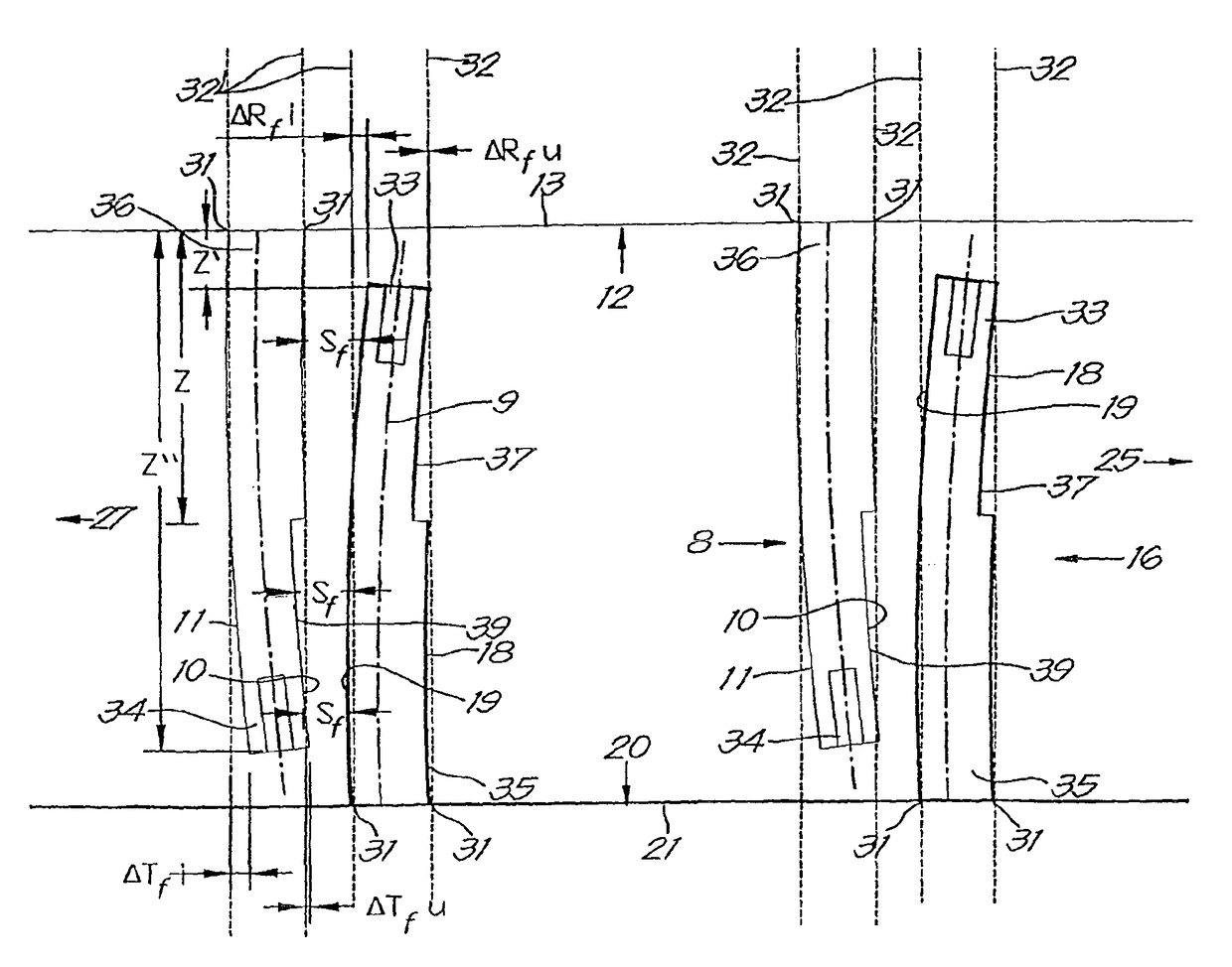
The invention is a scroll compressor that takes into account the deformations that occur when the compressor is under pressure and temperature while in service. The design improves the final local clearances to ensure more predictable and even results. The objective is to reduce the variation in the final profile of the local transverse internal clearances to zero, which improves efficiency and reduces leakage flow and compression loss. The reduced leakage rate also helps keep the operating temperatures in the scroll compressor lower.

Problems solved by technology

On the other hand, large internal clearances and in particular large local transverse internal clearances are also undesirable, as this would lead to a large leakage rate and pressure loss in the scroll compressor, with recompression of air or gas and would thus result in extra heat generation such that the efficiency of the scroll compressor is considerably negatively influenced.
A great difficulty here is that the internal clearances in the scroll compressor are far from a static fact.
This means that under the effects of the pressures and temperatures, the local instantaneous transverse internal clearance during nominal operation of the scroll compressor can easily become all too small at certain positions of the rotor in the stator when nothing is done.
In addition it is the case that at places where the local transverse internal clearance increases during operation of the scroll compressor, the internal leakage rate and the internal pressure loss between compressor chambers of the scroll compressor increase.
In brief, the internal clearances in a scroll compressor during nominal operation greatly affect the efficiency of the scroll compressor, and with the known scroll compressors it can be difficult to stay within the bounds and / or the circulating clearance profile of the local transverse internal clearances in the scroll compressor is highly variable or can be difficult to evaluate beforehand.
This problem is all the more acute as the pressures and temperatures in the scroll compressor rise, the powers increase or the speed of motion of the rotor in the stator increases.

Method used


Image

  • Scroll compressor
  • Scroll compressor
  • Scroll compressor

Examples


Embodiment Construction

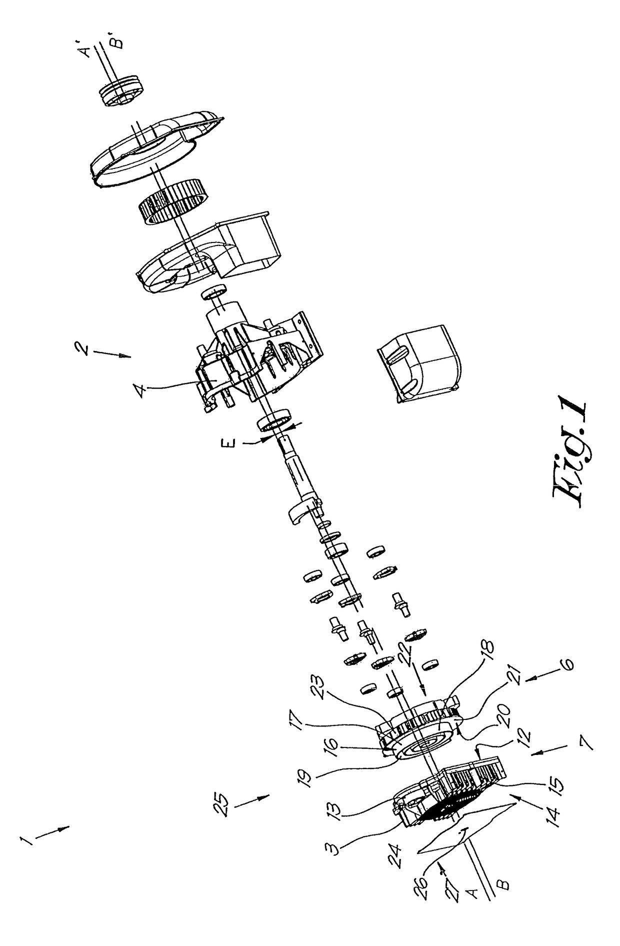
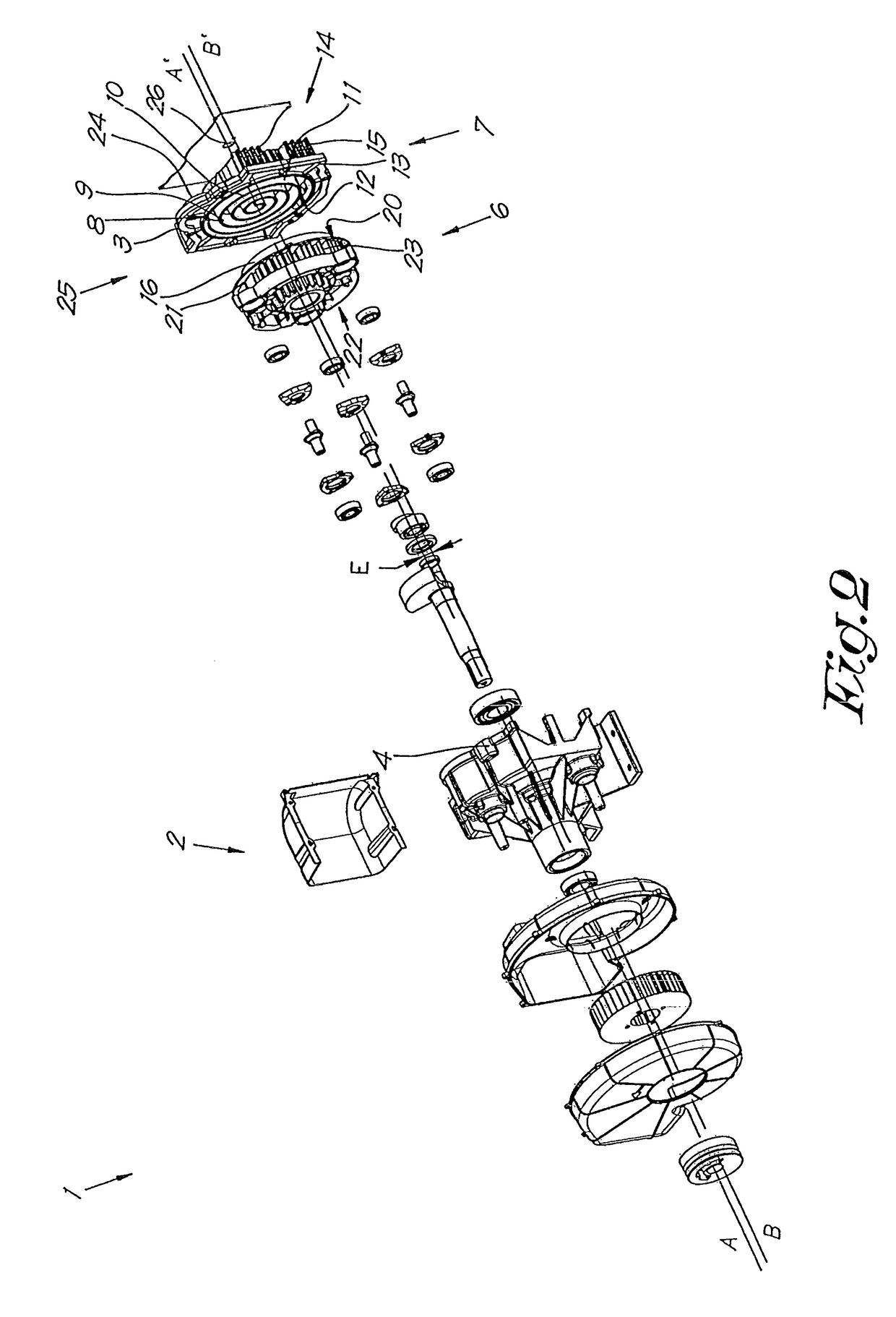
[0096]The elements shown in FIGS. 1 to 3 present an oil-free scroll compressor 1 in an expanded and assembled state and of a type to which the invention relates.

[0097]This scroll compressor 1 has a housing 2, which in this case is essentially composed of two sections, more specifically section 3 and section 4, which in the assembled state enclose a space 5 in which a rotor 6 is affixed.

[0098]Moreover, the section 3 forms a stator 7 that is affixed immovably in the housing 2 and which comprises a stationary stator scroll with a central stator axis AA′.

[0099]This stator scroll 8 is formed by a stator strip 9 with two stator flanks 10 and 11, respectively an outward stator flank 10 that is turned away from the centre or the central axis AA′ of the stator scroll 8, and an inward stator flank 11 that is turned towards the centre or towards the central axis AA′ of the stator scroll 8.

[0100]Moreover, the stator strip 9 is wound spirally along its length and affixed upright with a certain h...


PUM


Abstract

Scroll compressor with a stationary, stator scroll and a movable rotor scroll and a drive to move the rotor, whereby in each position places are formed with an instantaneous minimum opening between the rotor scroll and the stator scroll whereby at each height in a minimum opening there is a local transverse internal clearance (S), whereby at least one of the stator flanks or rotor flanks comprises an adapted flank section with an initial local stator flank deviation (ΔT0i, AT0u) or rotor flank deviation (ΔR0i / AR0u) that is different to zero at each point when the rotor is stationary, and during nominal operation of the scroll compressor corresponding instantaneous final local stator flank deviations (ΔTfi, ΔTfu) or rotor flank deviations (ΔRfi, ΔRfU) whose absolute values are smaller.

Description

[0001]The present invention relates to a scroll compressor.BACKGROUND OF THE INVENTION[0002]As is known a scroll compressor generally comprises the following elements:[0003]a housing;[0004]a stator that is immovably affixed in the housing and which comprises a stationary stator scroll with a central stator axis, whereby this stator scroll is formed by a stator strip with two stator flanks that is wound spirally along its length and which is affixed upright with a certain height on a stator plate;[0005]a rotor that is movably affixed in the housing and which comprises a rotor scroll with a central rotor axis, and this rotor scroll is formed by a rotor strip with two rotor flanks that is wound spirally along its length, and which is affixed upright with a certain height on a rotor plate and whereby the rotor scroll and the stator scroll are affixed in one another between the stator plate and the rotor plate;[0006]a low pressure inlet on the outside of the scroll compressor; and[0007]a...

Claims


Application Information

Patent Timeline
Patent Type & Authority Patents(United States)
IPC IPC(8): F04C18/02
CPCF04C18/0269F04C18/0215F04C18/0246F04C2270/17F04C2250/20
Inventor STOOP, KOENMOENS, BENJAMIN
Owner ATLAS COPCO AIRPOWER NV
Features
  • R&D
  • Intellectual Property
  • Life Sciences
  • Materials
  • Tech Scout
  • Unparalleled Data Quality
  • Higher Quality Content
  • 60% Fewer Hallucinations
Learn More