
Fluidized bed coating apparatus

a technology of coating apparatus and flue gas, which is applied in the direction of coating, material granulation, vibration granulation, etc., can solve the problems of ineffective atomization and liquid particle breakdown necessary for optimum coating, inefficiency of operation, and frequent cleaning, so as to achieve the effect of more efficiently and effectively coating particulate matter

Active Publication Date: 2018-09-11
SPRAYING SYST
View PDF12 Cites 0 Cited by
  • Summary
  • Abstract
  • Description
  • Claims
  • Application Information

AI Technical Summary

Benefits of technology

The invention is a fluidized bed coating system that can more effectively and efficiently coat particles with a coating fluid. It achieves this by atomizing the coating fluid and discharging it into the coating chamber, allowing for more complete interaction and coating of the particulate matter. Additionally, the system circulates the particulate matter with less tendency for clogging of the filter system.

Problems solved by technology

A problem with such fluidized bed coating systems is that the energy of the pressurized air utilized in atomizing the coating fluid tends to propel the coating particles upward past the particulate matter to be coated such as to prevent effective and efficient coating.
The energy of the pressurized air further tends to propel the coated particulate into the filter system at the upper end of the coating chamber, causing clogging, operating inefficiency, and the necessity for frequent cleaning.
Lowering the pressure of the atomizing air to minimize such problems, on the other end, results in ineffective atomization and liquid particle breakdown necessary for optimum coating.

Method used


Image

  • Fluidized bed coating apparatus
  • Fluidized bed coating apparatus
  • Fluidized bed coating apparatus

Examples


Embodiment Construction

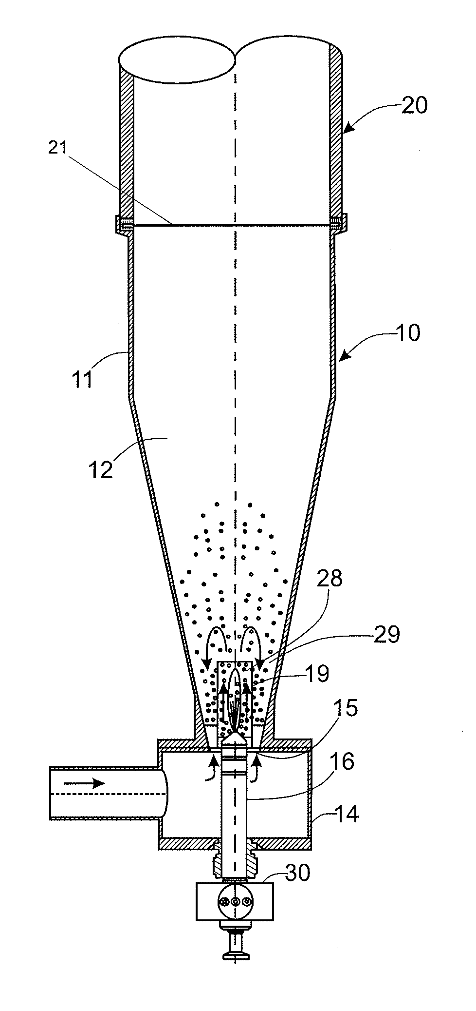
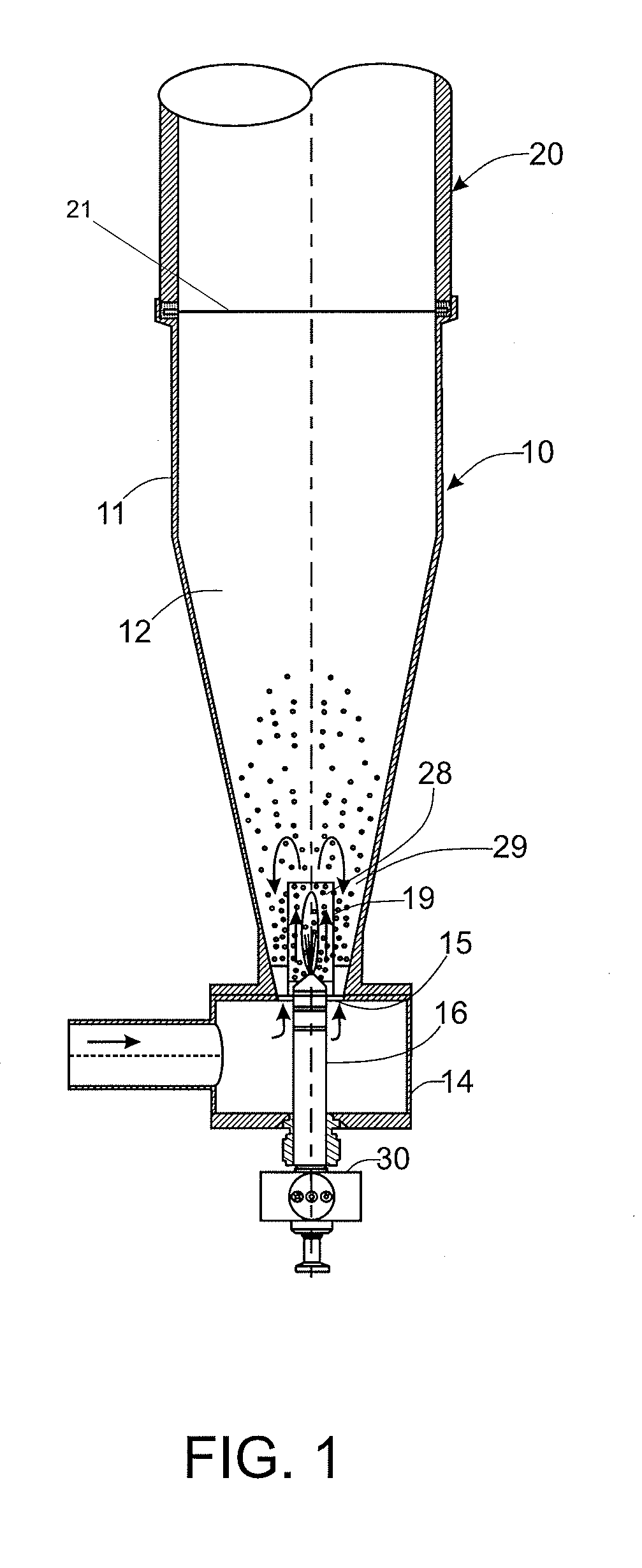
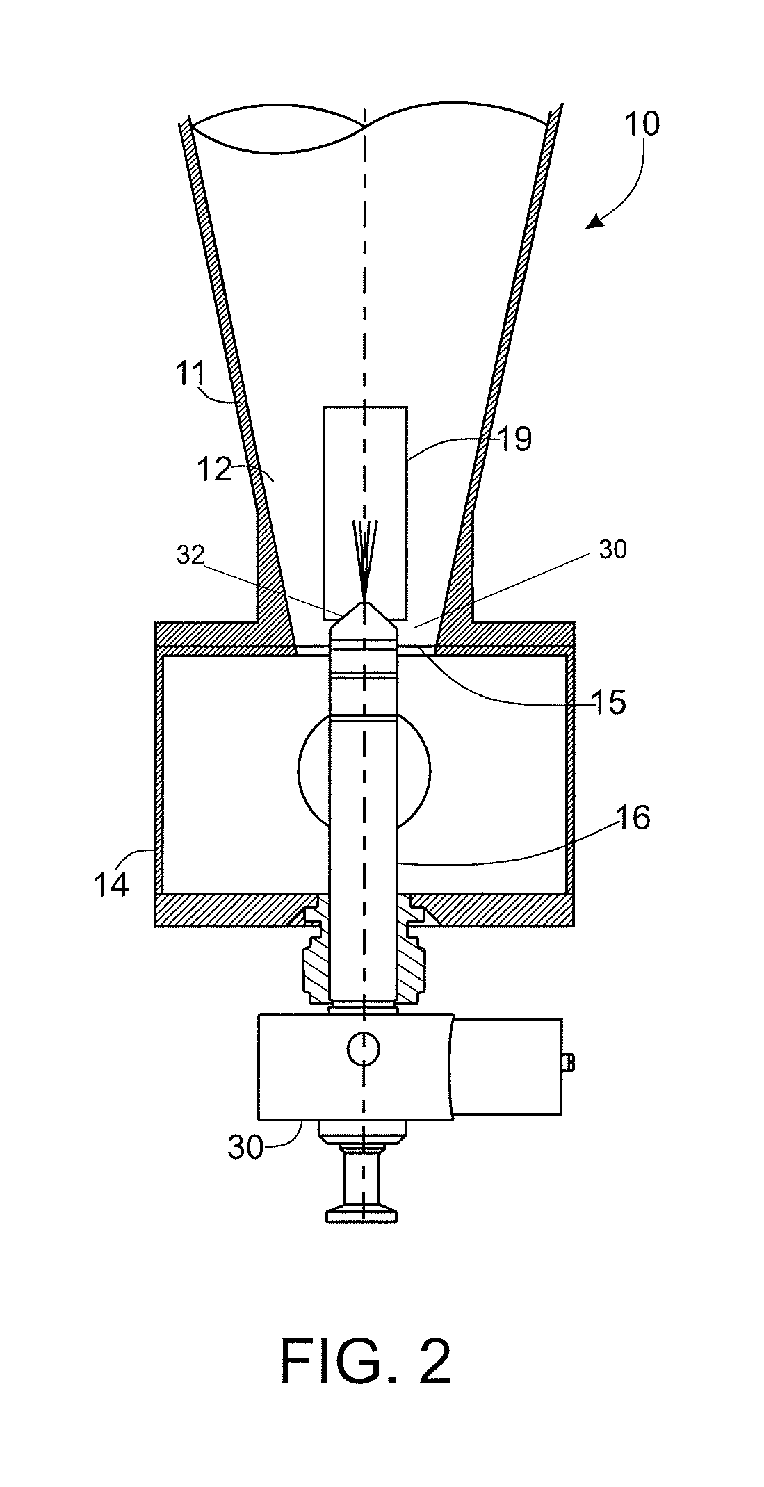
[0020]Referring now more particularly to FIGS. 1-4 of the drawings, there is shown an illustrative fluidized bed coating apparatus 10 in accordance with the invention. The illustrated apparatus 10 is of a type commonly referred to in the industry as a Wurster bottom spray coating machine. The illustrated coating apparatus 10 basically comprises a fluid bed bowl or vessel 11 which defines an upwardly expanding, conical coating chamber 12, a lower air inlet plenum 14 for communicating process air to the coating chamber 12, an orifice plate 15 between the air inlet plenum 14 and coating chamber 12, a central liquid spray nozzle 16 projecting upwardly through a central opening 18 (FIG. 3) in the orifice plate 15, and a cylindrical separator 19 disposed in upstanding surrounding relation to a discharge end of the spray nozzle 16. It will be understood by a person skilled in the art that particulate matter to be coated may be introduced into the coating chamber from an appropriate port in...


PUM

PropertyMeasurementUnit
volumeaaaaaaaaaa
pressureaaaaaaaaaa
sizeaaaaaaaaaa

Abstract

A fluidized bed coating apparatus for coating liquid onto the surfaces of particles directed into a coating chamber. A liquid spray nozzle assembly disposed below a hollow separator within the coating chamber includes an ultrasonic atomizer for atomizing coating liquid into a fine liquid particle cloud and a pressurized air directing air cap for forming the ultrasonically atomized fine liquid particle cloud into a cone shaped spray pattern and propelling the liquid particles through the separator into an upbed region of the coating chamber for recirculation in an outbed region, and through the separator. A cooling air passageway system is provided within the spray nozzle assembly for cooing the ultrasonic atomizer during operation.

Description

CROSS-REFERENCE TO RELATED APPLICATIONS[0001]This patent application claims the benefit of U.S. Patent Application No. 61 / 713,305, filed Oct. 12, 2012, which is incorporated by reference.FIELD OF THE INVENTION[0002]The present invention relates generally to fluidized bed coating systems, and more particularly, to a coating system in which an atomized coating liquid is directed upwardly into a coating chamber within which particles to be coated are circulated between upbed and downbed regions by upwardly directed airflow streams.BACKGROUND OF THE INVENTION[0003]Fluidized bed coating systems are known in which particles to be coated are circulated by an upwardly directed airstream through an upbed of particulate material to be coated and downwardly through an annular surrounding outbed of particulate material. Atomized coating liquid is directed centrally into the upbed for coating the particles as they travel upwardly. Airflow is generated within the coating chamber by drawing air th...

Claims


Application Information

Patent Timeline
Patent Type & Authority Patents(United States)
IPC IPC(8): B05C19/02B05B7/16B05B7/14B05B17/00B05B17/06B05B7/06B01J2/00B01J2/18B01J2/16
CPCB05B17/0646B01J2/006B01J2/16B01J2/18B05B7/066B05B7/1463B05B7/16B05B17/063B05B17/0623B05C19/02B05B7/1431Y10S118/05
Inventor FILICICCHIA, DANIEL J.HUFFMAN, DAVID C.SMITH, BRIAN K.SZCZAP, JOSEPH P.
Owner SPRAYING SYST
Learn More