Gasifiers with non radial tuyeres

Inactive Publication Date: 2005-07-05
DEDAR
View PDF7 Cites 9 Cited by
  • Summary
  • Abstract
  • Description
  • Claims
  • Application Information

AI Technical Summary

Benefits of technology

[0010]It will be appreciated that the gasifier of this invention is able to achieve better reduction of the fuel, by improving the interaction between the introduced air and the hot carbonised bed at the bottom of the gasifier chamber. This interaction may be achieved either solely by causing the introduced air to rotate along the axis of projection into the gasifier, or by additionally causing the introduced air to swirl around the lower region of the chamber. By adopting both of these measures of this invention, the interaction of the air with the bed at the bottom of the gasifier is much enhanced, so giving better control of the combustion of the fuel. In turn, this leads to more complete combustion in the oxidation zone, giving a greater oxygen deficiency in the reduction zone and

Problems solved by technology

In turn, this leads to more complete combustion in the oxidation zone, giving a greater oxygen deficie

Method used


Image

  • Gasifiers with non radial tuyeres
  • Gasifiers with non radial tuyeres
  • Gasifiers with non radial tuyeres

Examples


Embodiment Construction

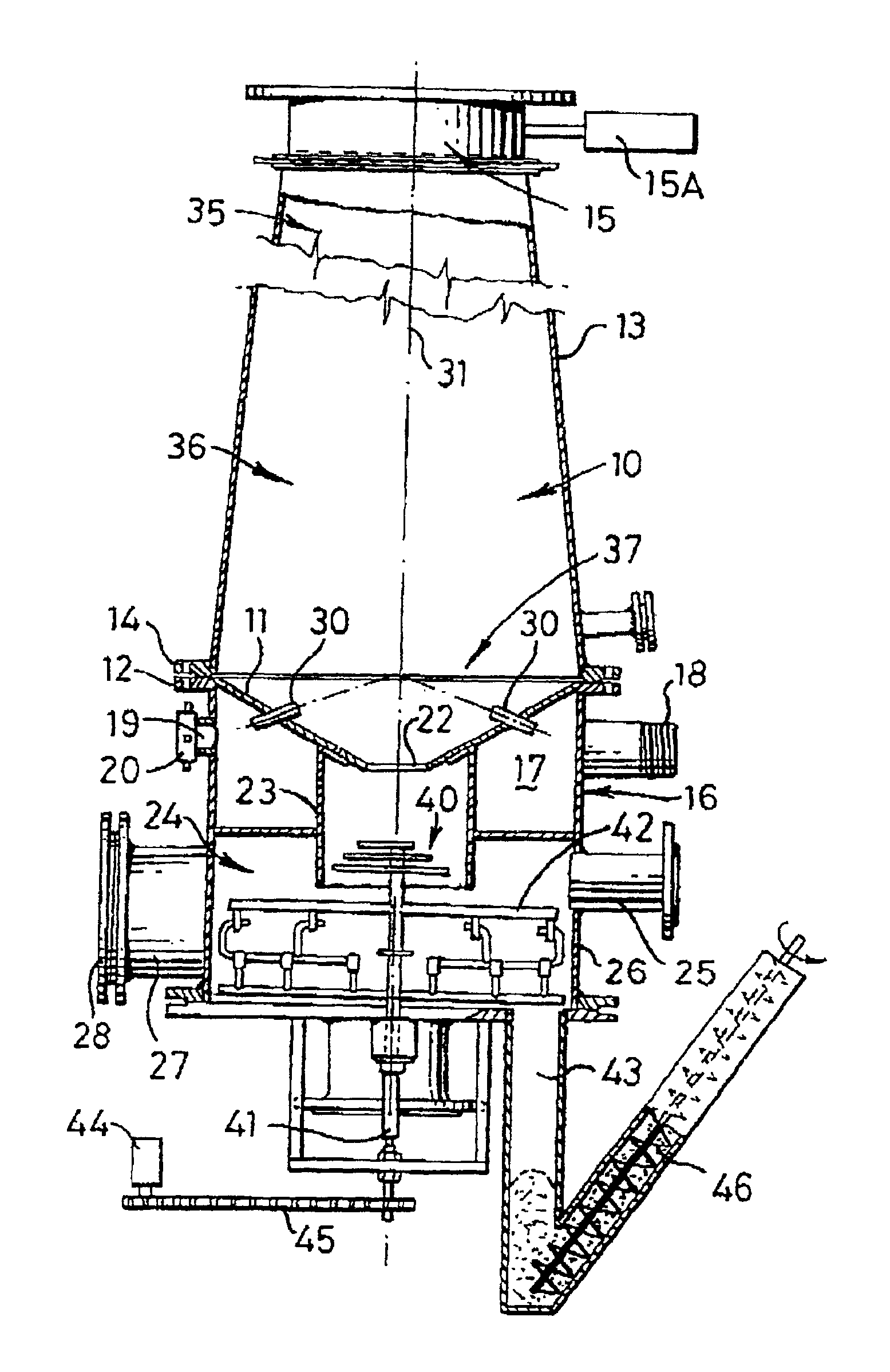
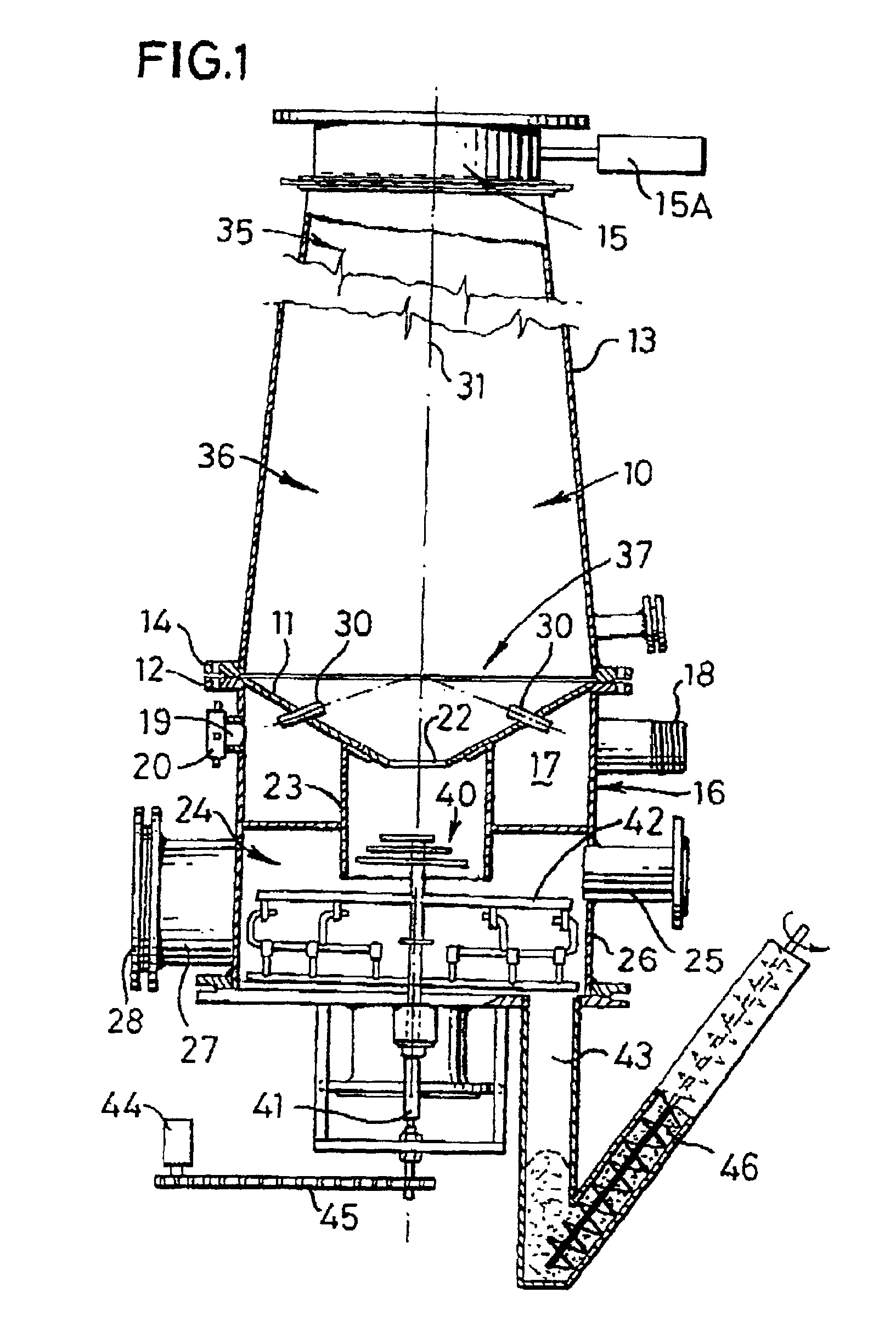
[0022]Referring initially to FIG. 1, there is shown diagrammatically an embodiment of gasifier arranged for the production of producer gas from a solid combustible material serving as a fuel, such as wood chippings, logs, coal or similar materials, poultry litter, dried sewage sludge or a refuse derived fuel. The gasifier comprises a combustion chamber 10 having a generally conical lower wall 11 provided with a flange 12 around its upper periphery. A hopper 13 has a corresponding flange 14 at its lower periphery and which is secured by bolts (not shown) to flange 12 of the lower wall 11. The upper end of the hopper 13 is closed by a slide valve assembly 15, which permits recharging of the hopper with more solid fuel whilst operation of the gasifier continues. An actuator 15A is mounted to one side of the hopper, to effect opening and dosing of the slide valve assembly.

[0023]In an alternative arrangement (not shown) the hopper has a simple lid which may be secured in position and a f...


PUM


Abstract

A gasifier for the manufacture of producer gas has a chamber (10) for the combustion of material, the chamber (10) being provided with a plurality of tuyeres (30) for the introduction of combustion air to the chamber. The tuyeres (30) are disposed at an acute angle to the wall of the chamber (10) so that air is directed both around and upwardly of the chamber. Each tuyeres (30) is configured to produce a jet stream wherein the air swirls along the length of the stream.

Description

CROSS REFERENCE TO RELATED APPLICATION[0001]The present application is the U.S. National Stage Application of International Application PCT / GB99 / 01671, filed May 27, 1999, which international application was published on Dec. 2, 1999 as International Publication WO99 / 61561 in the English language. The International Application claims priority of Great Britain Application 9811415.0, filed May 28, 1998.BACKGROUND OF THE INVENTION[0002]This invention relates to gasifiers and in particular to improvements in or relating to gasifiers whereby improved combustion may take place therewithin. The invention further relates to a method of operating a gasifier.[0003]The production of producer gas (a mixture of about 30% carbon monoxide and 70% nitrogen, though other gases may also be present) is usually performed with a so-called gasifier, in which pyrolysis is performed. The gasifier comprises a chamber provided with air inlets in such a way that the burning of fuel within the chamber take pla...

Claims


Application Information

Patent Timeline
IPC IPC(8): C10J3/22C10J3/02C10J3/26
CPCC10J3/22C10J3/26C10J3/42C10J2300/0956C10J2200/152
Inventor LING, MICHAEL JOHN ARCHER
Owner DEDAR
Why Eureka
Try Eureka