Roof edge structure for securing roofing materials

a technology for roof edges and roofing materials, applied in roof coverings, roofs, constructions, etc., can solve problems such as still flow or leakage into the ridge structure, and achieve the effects of quick drying, improved roof edge appearance, and easy air circulation

Inactive Publication Date: 2018-09-18
HEO BAL
View PDF37 Cites 5 Cited by
  • Summary
  • Abstract
  • Description
  • Claims
  • Application Information

AI Technical Summary

Benefits of technology

[0010]The invention is related to a roof edge construction where a small ridge is created along the edge of a roof. The ridge structure is a distinctive and separate feature of a roof than the roof ridge, which is the horizontal top area where two sloped roof areas meet in a sloped roof system. Here, a ridge structure refers to a slight elevation of surface along an axis along the edge of a roof, which results in a long and narrow hilltop along the eaves. The ridge structure of the present invention is typically formed on top of drip edges along the roof edge. A drip edge is a metal flashing or other overhanging component with an outward projecting lower edge, intended to control the direction of dripping water and help protect underlying building components. An edge of roofing material can be inserted through a slit along the ridge structure. Roofing material is generally the outermost protective layer on the roof, but the ridge structure can further protect the roofing materials from bird and wind damage.
[0011]The ridge structure has a drain hole or holes in addition to the slit. When water flows toward the slit side of the ridge structure, most water flows over the ridge structure because the slit is already filled by roofing materials and leaves a relatively small gap, but some may still flow or leak into the ridge structure. The water is drained through the drain hole or holes, and any water remaining inside the ridge structure may be quickly dried by air circulation. Such air circulation may be facilitated by making the ridge structure substantially hollow.
[0012]An object of the invention is to protect roofing materials from environmental damage while allowing water to exit from the roof freely. The ridge structure not only shields and affixes the roofing materials at the roof edge but also allows water to flow over it easily. Although the ridge structure may create an uphill for the water running down a pitched roof in relation to the roof surface, the uphill can still be a slight down slope in relation to the horizontal line if the pitch of the roof is steeper than that of the ridge structure. This unique characteristic can keep the water flow on a pitched roof primarily uninterrupted and deter the accumulation of debris along the ridge structure.
[0013]Another object of the invention is improving the appearance of a roof edge. The ridge structure covers the overhang of roofing materials at a roof edge and brings a better finished look. The slope design of the ridge structure can be modified to fit the overall look of a roof, and its surface may incorporate decorative patterns. The ridge structure can also create a high pressure area that pushes down on the roof at times of high wind, which can improve the aerodynamic stability of the roof.
[0014]A further advantage of the invention is that roofing materials can be affixed at the roof edge without nailing or screwing on top of the roofing materials. A nail or screw on top of roofing materials is exposed and highly prone to leak. Although sealant can be applied over the nail or screw, it will deteriorate over time. On the other hand, any nail or screw used to affix the ridge structure can be completely covered by roofing materials, and the roofing materials do not require a further affixing means because it is inserted into and secured by the ridge structure.

Problems solved by technology

When water flows toward the slit side of the ridge structure, most water flows over the ridge structure because the slit is already filled by roofing materials and leaves a relatively small gap, but some may still flow or leak into the ridge structure.

Method used


Image

  • Roof edge structure for securing roofing materials
  • Roof edge structure for securing roofing materials
  • Roof edge structure for securing roofing materials

Examples


Embodiment Construction

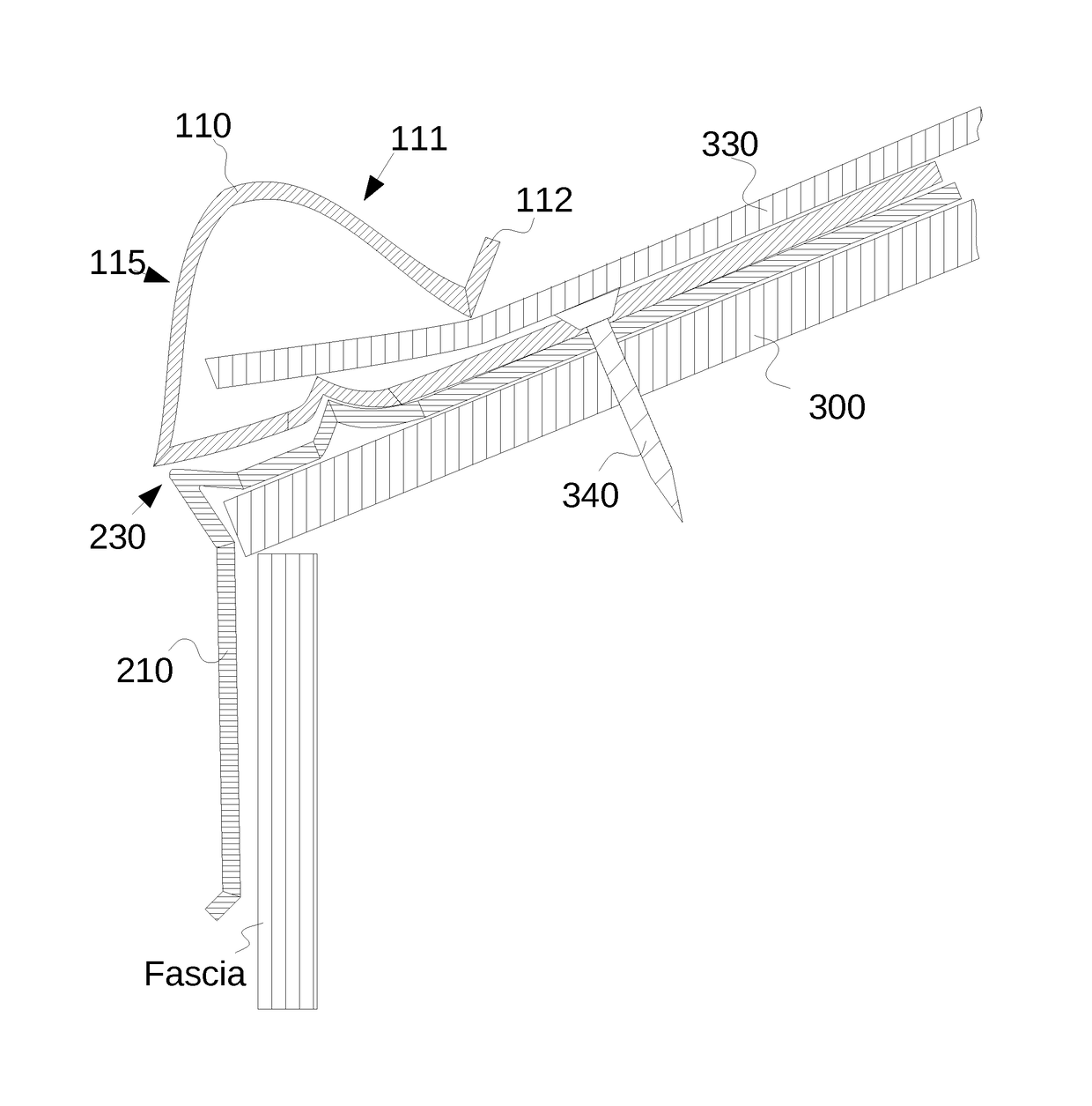
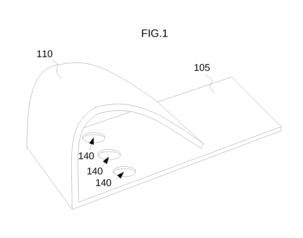
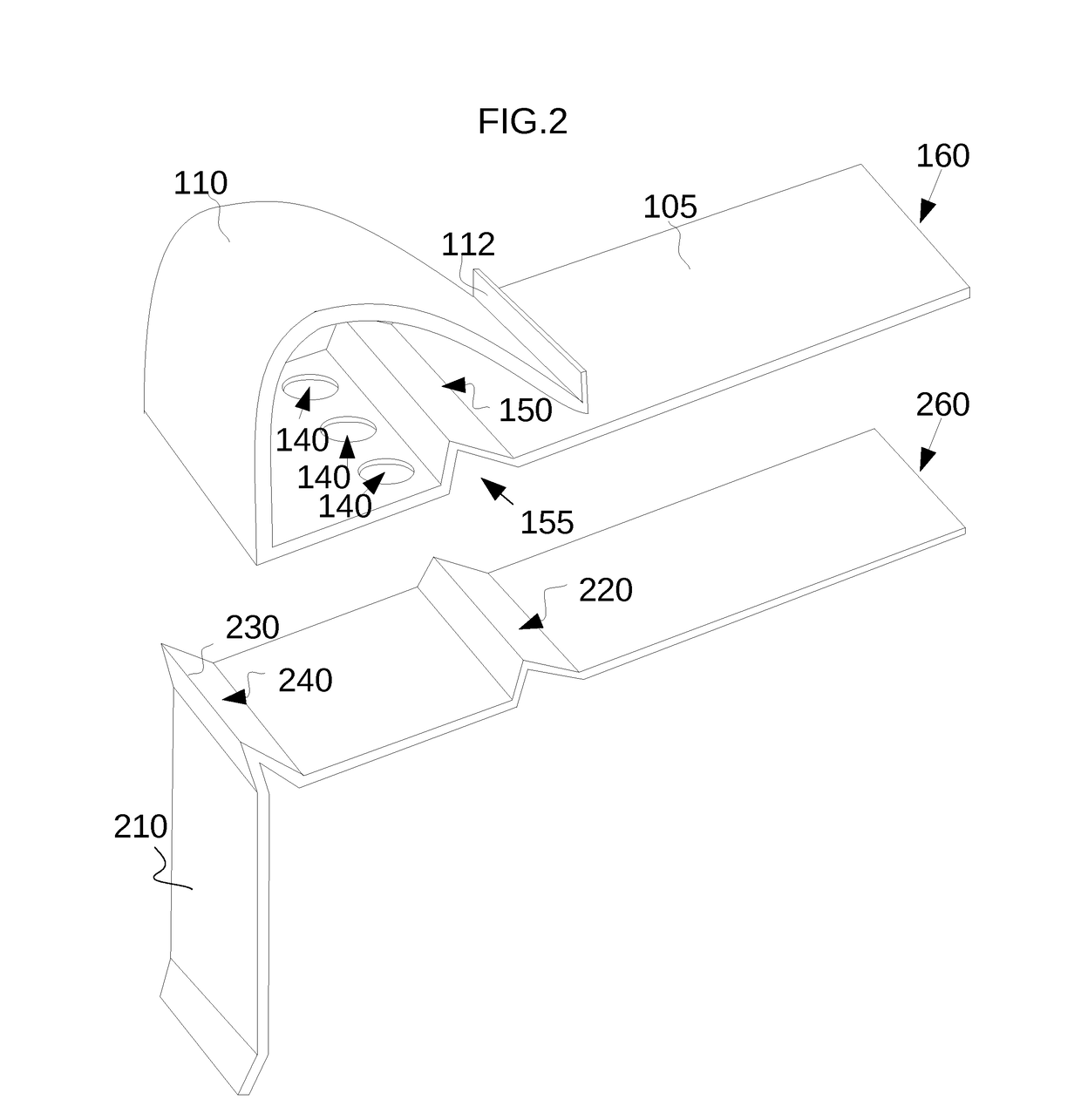
[0020]The invention is related to a roof edge construction where a ridge structure 110 is formed along the edge of a roof. An inner slope 111 of the ridge structure 110 faces the roof surface, and an outer slope 115 that faces the opposite. When installed on a building, an observer on a ground level outside the building would only see the outer slope 155 because the inner slope 110 faces the roof surface and is hidden from the observer's view. When installed on a pitched roof, the inner slope 111 may face upwardly to the sky, and the base panel 105 over which the slopes are situated generally has the same pitch as the roof. The bottom of the outer slope 115 is attached to the base panel 105 whereas the bottom of the inner slope 111 is not. The bottom of the inner slope 111 may touch or not touch the base panel 105, but there is always a long narrow cut between the bottom of the inner slope 111 and the base panel 105. The base panel has a drain hole or holes 140 between the bottoms o...


PUM


Abstract

A ridge structure at a roof edge, having a base panel lying on a roof surface and a hollow ridge structure over the base panel. The hollow ridge structure is constructed in a flat spring form along the eaves, and therefore one slope of the ridge faces the roof and the other slope the opposite direction. The slope facing the roof can be lifted to receive and secure roofing materials between the slope and the base panel. When water flows down the roof surface, most water flows over the ridge structure and the rest flows into the hollow space inside the ridge structure and drains through drain holes on the base panel.

Description

CROSS-REFERENCE[0001]This application is a continuation-in-part of prior application Ser. No. 15 / 411,961, filed Jan. 20, 2017. All materials in the prior Application are incorporated herein by reference.TECHNICAL FIELD[0002]The invention relates to the field of special arrangements or devices that are used in connection with roof coverings. More specifically, the invention relates to the devices and methods implemented at the edge of the roof in order to protect roof coverings from environmental damages such as bird, wind, and precipitation and at the same time to form drainage borders for directing water flow away from the building structure. The invention further relates to roofing edge strips that provide a securing means for roof coverings along the edge of a roof.BACKGROUND ART[0003]A roof of a modern building is typically composed of multiple elements including framing, insulation, ventilation, sheeting, flashing and covering. These elements can independently or together suppo...

Claims


Application Information

Patent Timeline
Patent Type & Authority Patents(United States)
IPC IPC(8): E04D13/15E04D13/04
CPCE04D13/0459E04D13/15E04D1/3405E04D2001/3482E04D2001/3417E04D2001/345E04D2013/0468E04D2001/3458
Inventor HEO, BAL
Owner HEO BAL
Why Eureka
Try Eureka