Devices and methods for temporary mounting of parts to bone

a technology of temporary mounting and parts, which is applied in the field of temporary mounting devices to bone, can solve the problems of compromising the accuracy of the tracker, weak attachment to the bone, and difficult to remove the temporary mounting device, so as to improve the accuracy of the attached apparatus and be easy to remove from the bone

Active Publication Date: 2018-09-25
GLOBUS MEDICAL INC
View PDF547 Cites 8 Cited by
  • Summary
  • Abstract
  • Description
  • Claims
  • Application Information

AI Technical Summary

Benefits of technology

[0004]To meet this and other needs, devices, systems, kits, and methods for temporarily mounting an apparatus, such as a tracker, to bony structures are provided. In particular, the temporary devices may provide for multiple points of fixation to the bone, thereby providing a strong attachment to the bone and improving the accuracy of an attached apparatus, such as a tracker for surgical navigation. The temporary mounting devices may also include features, such as stops including protrusions and arched regions, for example, which prevent the temporary mounting device from accidentally being advanced too far into the bony structure. The design of the temporary mounts can help to protect the bone and surrounding areas and can be easier to remove from the bone when the surgical navigation and / or surgical procedure are completed.
[0006]The temporary mount may include one or more of the following features, for example. Each of the plurality of prongs may include a protrusion extending therefrom configured to act as a stop to prevent over-insertion of the mount in the bony structure. The protrusions may be in the form of hill-shaped prominences positioned along the length of the prong (e.g., spaced apart from a distal most end). The plurality of elongated prongs may extend a length greater than a length of the base member (e.g., the prongs are longer than the base member portion of the mount such that the height of the device is primarily due to the height of the prongs). The plurality of elongated prongs may be in the form of a first prong and a second prong, and a transition from the first prong to the second prong may be arched or curved to act as an ultimate stop to prevent over-insertion of the mount in the bony structure. An arched stop may be provided between each prong. The plurality of elongated prongs may include a first prong, a second prong, a third prong, and a fourth prong, where a first arched portion between the first prong and the second prong has a first distance from the top face, and a second arched portion from the second prong to the third prong has a second distance from the top face, the second distance being different from than the first distance. In particular, the second distance may be greater than the first distance or vice versa. The arched portions on opposite sides of the device may be the same or substantially equivalent. In some embodiments, the mount may also include an outer sleeve having a hollow interior configured to engage an outer surface of the base member and / or a portion of one or more outer surfaces of the prongs. The outer sleeve may be configured to slide or rotate, for example, in order to compress the prongs inwardly toward one another. Each of the plurality of prongs may have a textured inner surface configured to resist extraction from the bone. Each of the plurality of prongs may have a sharpened distal-most tip configured to penetrate the bony structure. When the base member is impacted by the insertion device, the temporary mount may provide an audible sound, as each of the prongs is driven downward, and the frequency of the audible sound may change indicating the relative position of the mount in the bone (e.g., when the mount is fully seated in the bone structure). The mount is configured to hold and engage a portion of a trackable reference array, which may assist in surgical navigation, for example, with a surgical robot.

Problems solved by technology

These devices, however, may only provide for a single point of fixation to the bone, thereby providing a weak attachment to the bone and potentially compromising the accuracy of the tracker.
In addition, traditional devices may be accidentally advanced too far into the bony structure, which can damage the bone or surrounding areas or make it difficult to remove the temporary mounting device, which is embedded too deeply into the bone, after the procedure is completed.

Method used


Image

  • Devices and methods for temporary mounting of parts to bone
  • Devices and methods for temporary mounting of parts to bone
  • Devices and methods for temporary mounting of parts to bone

Examples


Embodiment Construction

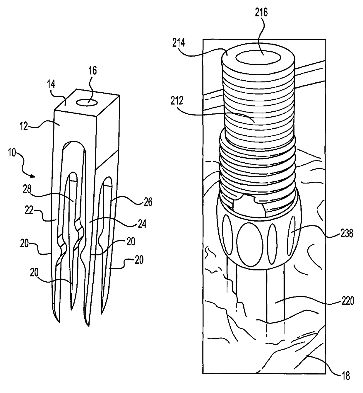
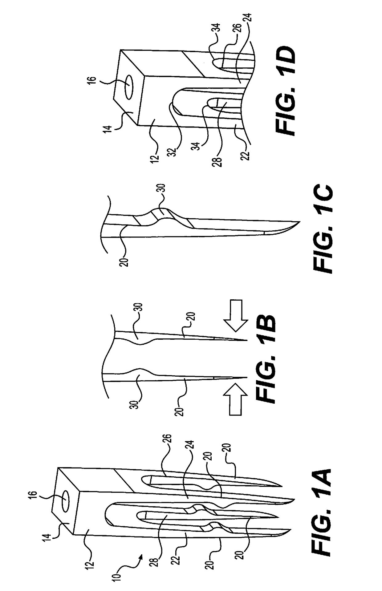
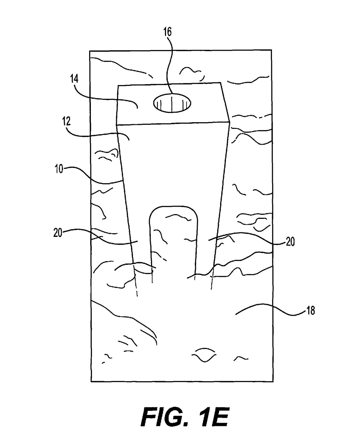
[0017]Embodiments of the disclosure are generally directed to devices, systems, kits, and methods for temporarily mounting an apparatus, such as a tracker for surgical navigation, to bony structures. Specifically, the temporary mounts may include a plurality of prongs, legs, spikes, tines, or the like, extending from a base member, which provide for multiple points of fixation to the bony structure. The bony structure may include any bones, bony segments, bony portions, bone joints, or the like of a patient. For example, the bony structure may include areas from a bone from the spine, such as a vertebra, a hip bone, such as an ilium, a leg bone, such as a femur, or a bone from an arm, such as a distal forearm bone or a proximal humerus, or any other bone in a mammal. In an exemplary embodiment, the bony structure or bone includes one or more vertebrae in the spinal column of a human patient. Providing for multiple points of fixation allows for a stronger attachment to the bone and m...


PUM


Abstract

Devices and methods for temporarily affixing a surgical apparatus to a bony structure. The temporary mount includes a base member having a top face configured to be impacted by an insertion device and a plurality of elongated prongs extending downwardly from the base member and configured to engage a bony structure. The prongs are separated a distance from one another, and the prongs are configured to move inwardly toward one another when driven downward into the bony structure.

Description

FIELD OF THE INVENTION[0001]The present disclosure generally relates to devices and methods to temporarily mount an apparatus to bone. For example, these temporary mounts may be suitable for attaching an apparatus, such as a trackable reference array, to a bony structure in a patient's body to provide a reference point during surgical navigation.BACKGROUND OF THE INVENTION[0002]During surgery, it may be necessary to temporarily mount an apparatus to exposed bone. For example, when using surgical navigation, it may be necessary to attach a tracker, such as a trackable reference array of optical markers, to the patient for accurately tracking the position of tools relative to the surgical site. If bone is the surgical target, such as when inserting a bone screw or the like, then attaching the reference array to bone provides better accuracy than attaching the reference array to surrounding soft tissues and more accurately tracks the position of the surgical tools relative to the bone....

Claims


Application Information

Patent Timeline
Patent Type & Authority Patents(United States)
IPC IPC(8): A61B17/56A61B34/20A61B90/50A61B90/10A61B90/00
CPCA61B34/20A61B17/56A61B90/10A61B90/39A61B90/50A61B2090/3991A61B2034/2068A61B2090/3916A61B2090/3983
Inventor BARTELME, MICHAELCRAWFORD, NEIL R.FOSTER, MITCHELL A.MAJOR, CHRISTHEODORE, NICHOLAS
Owner GLOBUS MEDICAL INC
Why Eureka
Try Eureka