Pulley device for tensioner or idler

a technology of idler and pulley, which is applied in the direction of rigid support of bearings, gearing, hoisting equipment, etc., can solve the problems of difficult installation of elastic rings, inability to maintain their position, and insufficient solution, so as to reduce costs, facilitate manufacturing, and facilitate assembly

Active Publication Date: 2018-09-25
AB SKF
View PDF12 Cites 7 Cited by
  • Summary
  • Abstract
  • Description
  • Claims
  • Application Information

AI Technical Summary

Benefits of technology

[0008]More particularly, the present invention aims to provide a pulley device easy to manufacture, to assemble and of reduced cost.
[0010]The implementation of the axial retention member is eased by the fact that it is fixed to the spacer. The risk of loss of the member is reduced. Thanks to the retention means, the screw is efficiently axially retained in the spacer. Moreover, standard fastening screws can be used, without any groove. The fixing portion permits the fixation of the retention member to the spacer.
[0014]Such a design of retention means ensures an efficient retention of the screw relative to the spacer, without impairing the ease of assembly.

Problems solved by technology

However, this solution has the drawback that the elastic ring is difficult to install and its position is not always maintained.
This solution is not fully satisfactory since it requires a special design of the screw.
Moreover, there is a risk of loss of the retainer ring before mounting of the fastening screw when assembling the device.

Method used


Image

  • Pulley device for tensioner or idler
  • Pulley device for tensioner or idler
  • Pulley device for tensioner or idler

Examples


first embodiment

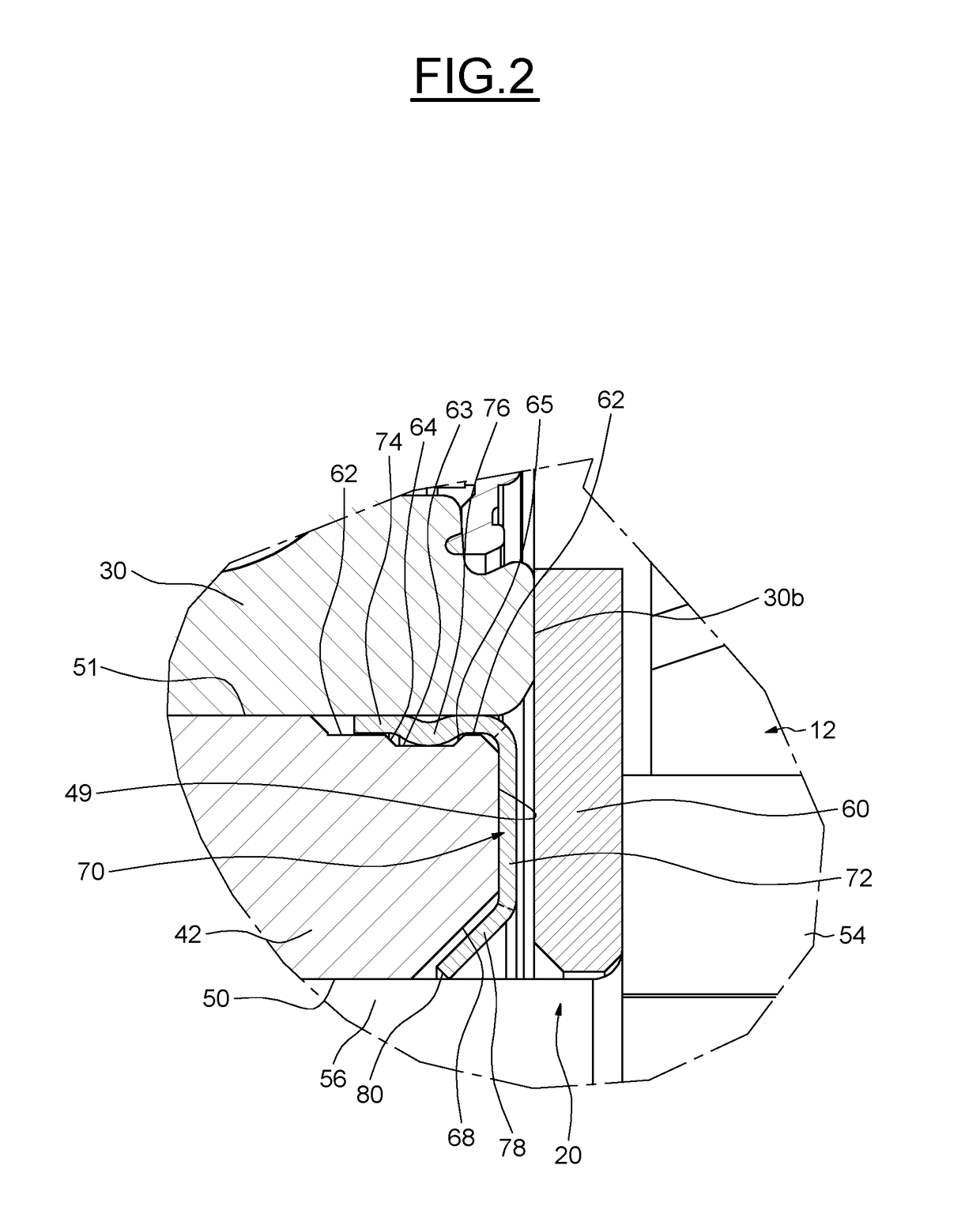
[0049]Member 92 provides an annular radial support surface 94 mounted to axially face the front surface 49 of spacer 18. Member 92 also provides an annular axial fixing portion 104 mounted on the outer surface 51 of the spacer 18. Member 92 provides a collar 108 mounted in contact with the bearing 14. Member 92 further provides retention means for the screw 20, the means being an annular tongue 112. Structurally, the axial retention member 92 mainly differs from the member 70 of the first embodiment in that it is provided with the collar 108. In this illustrated example, the support portion 94 is not in direct contact with the front surface 49. The support portion 94 is in direct contact with the head 54 of the fastening screw 20. The use of a ring 60 of the device in FIG. 1 is prevented in this embodiment.

[0050]The outer surface 51 of spacer 18 provides an annular groove 96. Groove 96 is delimited by two opposite frustoconical surfaces 98 and 100.

[0051]Fixing portion 104 provides t...

third embodiment

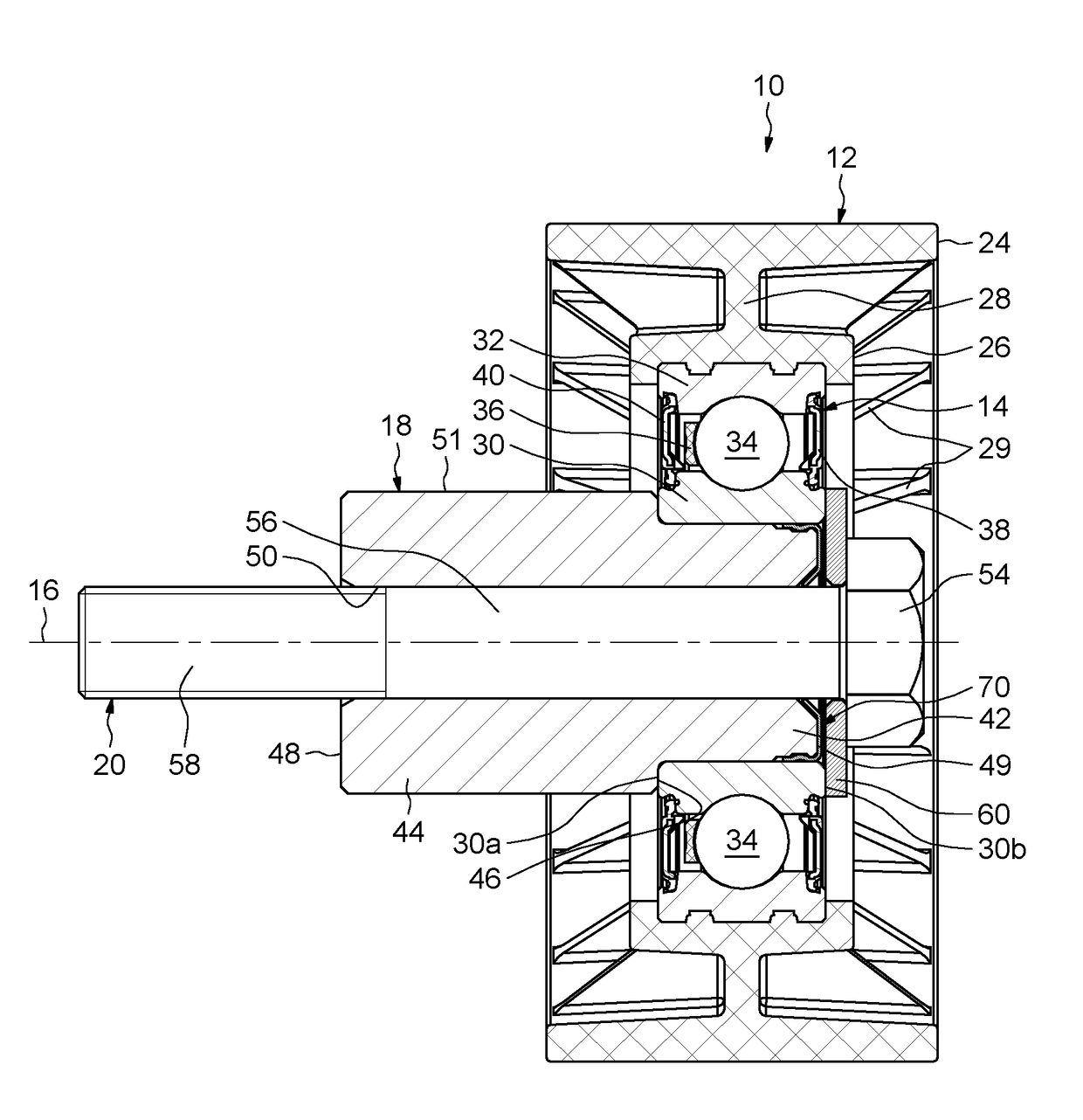
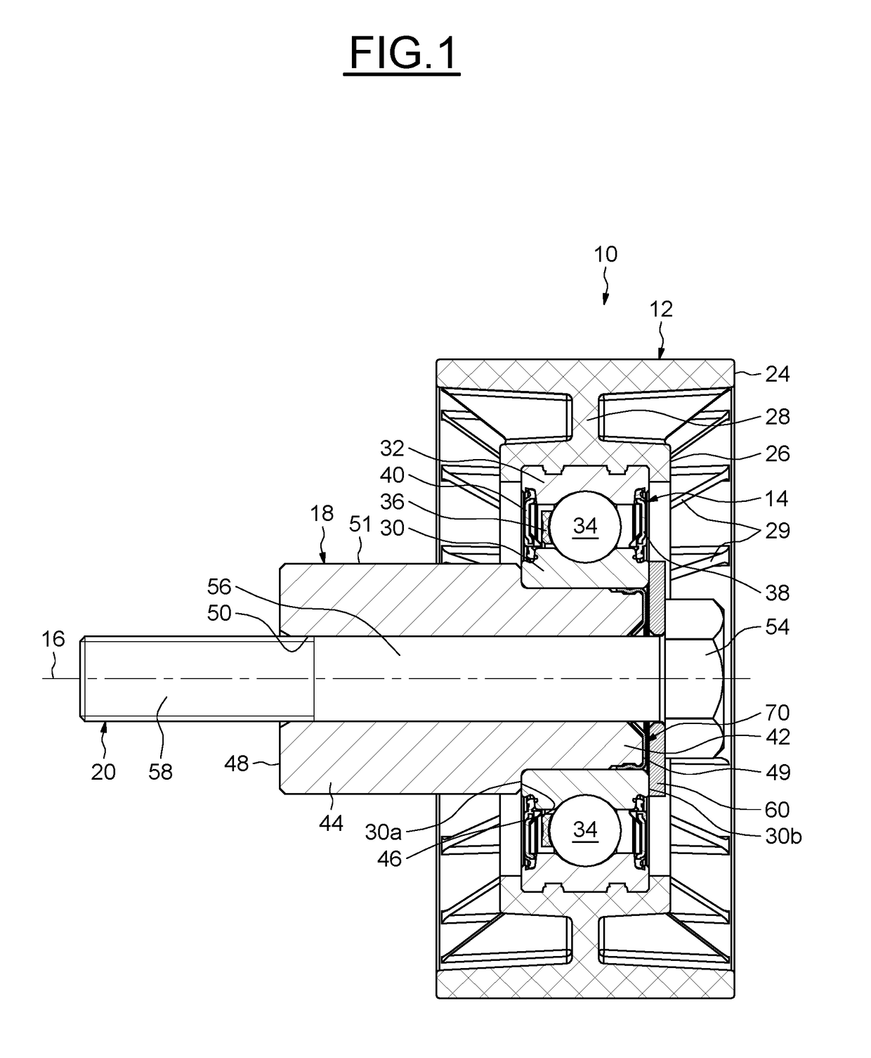
[0056]FIG. 5 illustrates a pulley device 120, in which the same elements have the same references.

[0057]This embodiment differs from the embodiment of FIG. 1 in that an axial retention member 122 is in contact against a front surface 48 of spacer 18, replacing the axial retention member 70 of the first embodiment which is in contact against the front surface 49. The axial retention member 122 presents a similar structure to the axial retention member of the first embodiment.

[0058]Bore 50 of spacer 18 provides a chamfer 121 open to the surface 48. Chamfer 121 is located axially of the side of the screw head 54. Axial retention member 122 provides an annular radial support portion 124 mounted in axial contact against the surface 48. Axial retention member 122 provides an annular radial support portion 126 mounted in radial contact against the outer surface 51. Axial retention member 122 provides an annular tongue 128 disposed radially in the chamfer 121. Alternatively, the tongue 128 ...


PUM


Abstract

The invention relates to a pulley device for tensioner or idler for a belt or a chain having a pulley, a bearing, a spacer supporting the bearing and including a through bore, a fastening screw extending in the bore, and an axial retention member for the screw, the axial retention member being fixed to the spacer and providing a retention member that cooperates with the screw.

Description

CROSS-REFERENCE TO RELATED APPLICATIONS[0001]This application claims priority to French patent application no. 1553964 filed on May 4, 2015, the contents of which are fully incorporated herein by reference.FIELD OF THE INVENTION[0002]The present invention relates to the field of pulley devices for tensioner or idler designed to cooperate with a chain or a belt, for example a timing belt for an internal combustion automobile motor.BACKGROUND OF THE INVENTION[0003]Such devices are typically used to continuously maintain tension on the chain or the belt in a specific range of tension value or to locally modify the path taken by the chain or belt. This is called tensioner or idler, respectively. In idlers, the pulley is rotatably mounted on a screw or an axle via a bearing, the idler being fixed directly or indirectly to an engine block or to an element of an idler assembly, such as an arm or an eccentric. The bearing is a mechanical device for implementing the pivot connection between ...

Claims


Application Information

Patent Timeline
Patent Type & Authority Patents(United States)
IPC IPC(8): F16H55/36F16C35/073F16H7/20F16C13/00
CPCF16H55/36F16C35/073F16H7/20F16C2361/63F16C13/006F16H7/08F16H55/50
Inventor LESCORAIL, ROMUALDLIEGE, FREDERIC
Owner AB SKF
Why Eureka
Try Eureka