
Heat treatment device

a treatment device and heat treatment technology, applied in the field of heat treatment devices, can solve the problems of limited topical application, patient compliance, drug interactions, etc., and achieve the effect of limiting infections during surgery and accelerating wound healing

Inactive Publication Date: 2018-10-02
EMPIRE TECH DEV LLC
View PDF43 Cites 3 Cited by
  • Summary
  • Abstract
  • Description
  • Claims
  • Application Information

AI Technical Summary

Benefits of technology

[0003]Thermal based treatments can be designed for use in treating a variety of conditions. Certain advantageous embodiments disclosed herein reduce or eliminate various problems associated with current thermal devices or non-thermal treatments such as the use of antibiotics for treating certain infections. For example, using antibiotics is subject to potential disadvantages of bacterial resistance, allergic reactions, drug interactions, limited topical application, patient compliance, and other limitations. Additionally, thermal treatments can be used not only to treat external infections and opened, internal infections, but also to prevent infection by applying controlled heat to a wound. This can help limit infections during surgery if heat is applied before and / or immediately after surgical closure. Further, thermal treatments can be used for a variety of non-infectious conditions, such as to accelerate wound healing or treat skin cracks, tendinitis, pressure sores, alopecia, or ulcers, to name but a few examples.
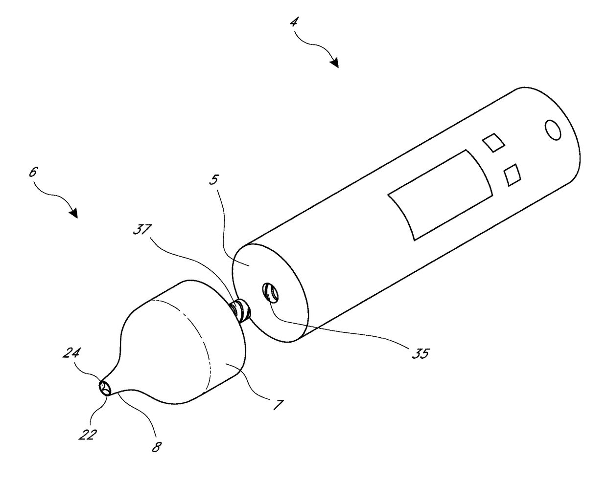
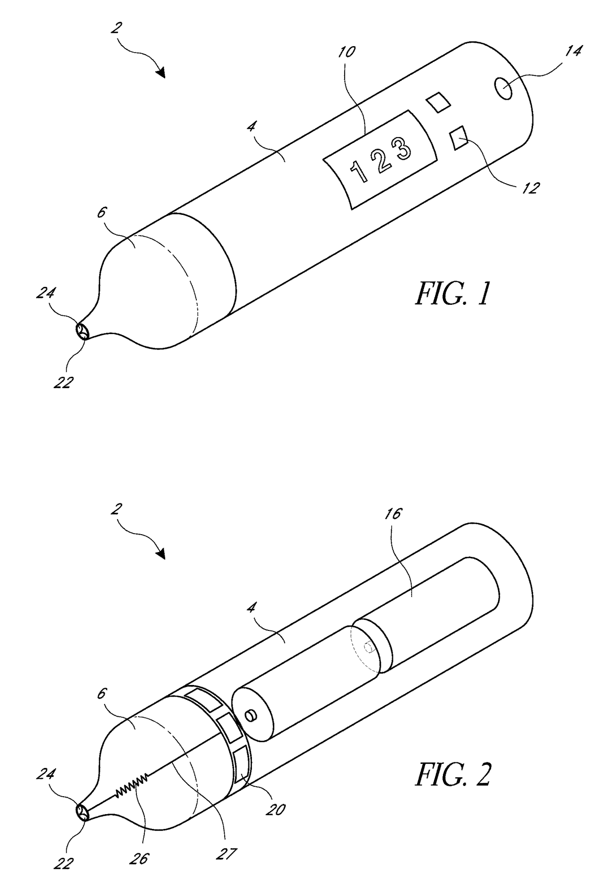
[0004]Different treatments may be improved by use of different embodiments of a heat treatment device. Some treatments can benefit from embodiments comprising a rigid tip that can allow for precise application of heat. Other treatments can benefit from embodiments comprising conformable tips that can mold to specific contours of a treatment area. In some embodiments of a heat treatment device an application tip can maintain a regulated temperature across the contact surface, even as heat flows into the treatment area.
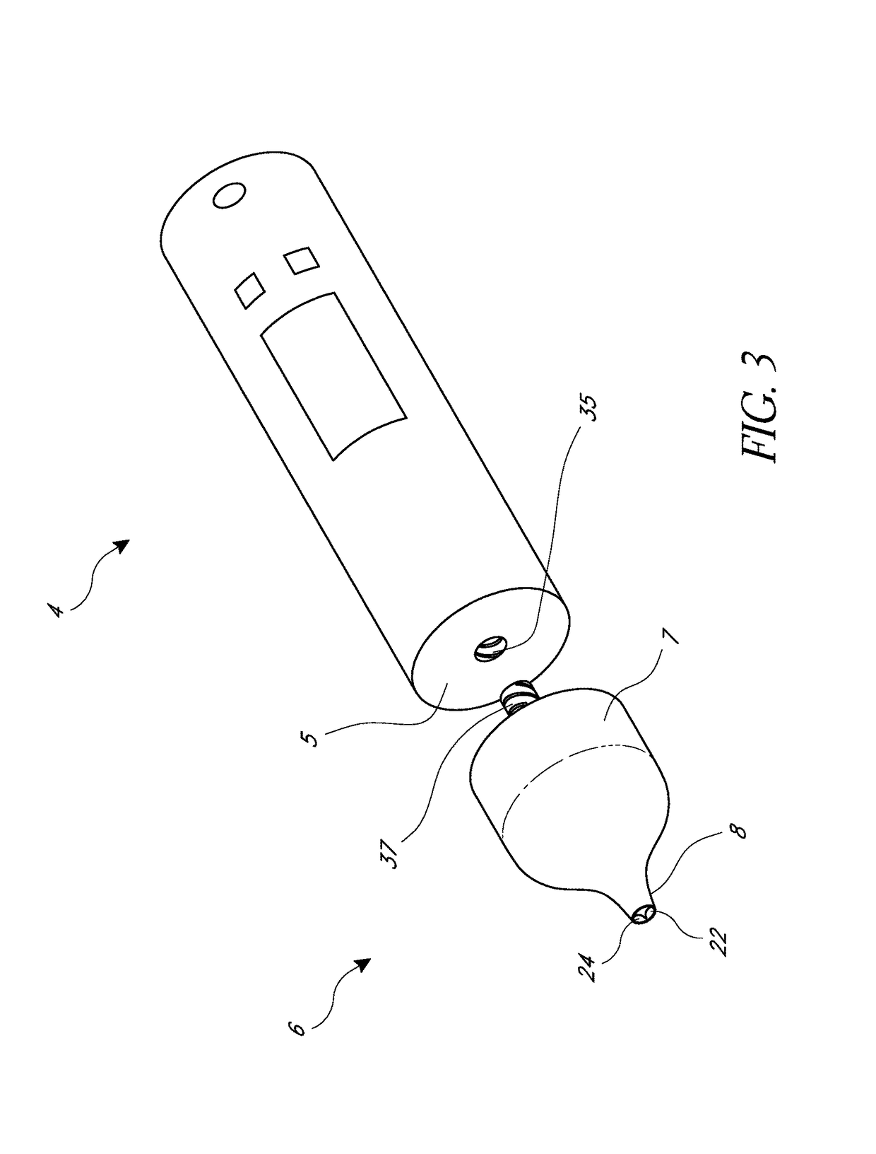
[0017]In some embodiments, the replaceable tip portion can further comprise a conducting element that extends through the replaceable tip portion and is electrically coupled with the connector portion and the heating element. In further embodiments, the replaceable tip portion can comprise a connector jacket that is engageable with and removable from the connector portion, and a tip jacket that is engageable with and removable from the contacting portion. The connector jacket and the tip jacket can attach to the replaceable tip portion for preserving sterility of the replaceable tip portion when disengaged from the heat treatment device.

Problems solved by technology

For example, using antibiotics is subject to potential disadvantages of bacterial resistance, allergic reactions, drug interactions, limited topical application, patient compliance, and other limitations.

Method used


Image

  • Heat treatment device
  • Heat treatment device
  • Heat treatment device

Examples


Embodiment Construction

[0056]In the following detailed description, reference is made to the accompanying drawings, which form a part hereof. In the drawings, similar symbols typically identify similar components, unless context dictates otherwise. The illustrative embodiments described in the detailed description, drawings, and claims are not meant to be limiting. Other embodiments may be utilized, and other changes may be made, without departing from the spirit or scope of the subject matter presented herein. It will be readily understood that the aspects of the present disclosure, as generally described herein, and illustrated in the Figures, can be arranged, substituted, combined, separated, and designed in a wide variety of different configurations, all of which are explicitly contemplated herein.

[0057]This description relates generally to heat treatment devices that have a heatable tip configured to maintain a desired temperature when placed in contact with a treatment surface. In some embodiments, ...


PUM


Abstract

A heat treatment device with a handle portion, a tip portion, a power source, and a heating element. The tip portion is heatable to a desired temperature and can be positioned against an affected area for therapeutic treatment. The device can also have control circuitry that can adjust a current flowing to the heating element to regulate the treatment temperature.

Description

CROSS-REFERENCE TO RELATED APPLICATIONS[0001]This application is a U.S. National Phase under 35 U.S.C. § 371 of International Application PCT / US2012 / 033923, filed Apr. 17, 2012, which designated the U.S. and which is hereby expressly incorporated by reference in its entirety.BACKGROUND OF THE INVENTION[0002]Applying heat to the site of an infection or other condition can be an effective form of treatment. Current heat treatments may involve application of warm compresses or other devices that have difficulties applying a precise, regulated temperature to the entire site of treatment.SUMMARY OF THE INVENTION[0003]Thermal based treatments can be designed for use in treating a variety of conditions. Certain advantageous embodiments disclosed herein reduce or eliminate various problems associated with current thermal devices or non-thermal treatments such as the use of antibiotics for treating certain infections. For example, using antibiotics is subject to potential disadvantages of ba...

Claims


Application Information

Patent Timeline
Patent Type & Authority Patents(United States)
IPC IPC(8): A61F7/00A61B90/00
CPCA61F7/007A61B2090/065A61F2007/0096A61F2007/0072A61F2007/0087A61F2007/0054
Inventor PEZZI, KEVIN ANTHONY
Owner EMPIRE TECH DEV LLC
Learn More