Fuel pump

a fuel pump and pump body technology, applied in the direction of liquid fuel engines, piston pumps, positive displacement liquid engines, etc., can solve the problem of difficult movement of the piston in an ascending direction, and achieve the effect of low fuel pressure and higher fuel pressur

Inactive Publication Date: 2018-10-02
TOYOTA JIDOSHA KK
View PDF17 Cites 0 Cited by
  • Summary
  • Abstract
  • Description
  • Claims
  • Application Information

AI Technical Summary

Benefits of technology

[0008]However, with this configuration, since the mover and the counterweight are connected to each other via the spring, there is concern about the occurrence of the following disadvantage. That is, when pressurizing fuel in a pressurizing chamber, the load applied to the mover becomes greater than that applied to the counterweight. In this case, the plunger is difficult to move in an ascending direction (the moving direction of the plunger when the plunger moves in a direction to reduce the volume of the pressurizing chamber). Therefore, the entire reciprocating range of a reciprocating body constituted by the mover, the spring, and the counterweight is lowered in a descending direction of the plunger so that the top dead center position of the plunger is lowered. When the top dead center position of the plunger is lowered, the dead volume in the pressurizing chamber (the value equal to the volume in the pressurizing chamber when the plunger moves up to the top dead center) increases. Accordingly, even if the plunger is moved by the same stroke amount, the pressure rise of the fuel decreases compared to that before the top dead center position of the plunger is lowered. Therefore, the stroke amount of the plunger should be increased in order to obtain the same pressure rise so that there is a possibility of a reduction in pump efficiency.
[0009]Therefore, in view of these circumstances, the present disclosure provides a fuel pump that can suppress a reduction in pump efficiency that is caused by the lowering of a top dead center position of a plunger.
[0013]Therefore, according to the configuration described above, it is possible to suppress a reduction in pump efficiency that is caused by the lowering of the top dead center position of the first plunger. In the fuel pump, the third spring and the fourth spring may both be disposed in a pre-compressed state.
[0014]The greater the spring constant of the third spring and the fourth spring, the more the movement of the plate in the descending direction of the first plunger is suppressed and, therefore, the higher the effect of suppressing the lowering of the top dead center position of the first plunger.
[0015]Herein, as described above, when the plate is lowered in the descending direction of the first plunger, one of the third spring and the fourth spring sandwiching the plate therebetween is compressed in the descending direction of the first plunger, while the other is expanded in the descending direction of the first plunger. It is assumed that the lowering amount of the plate in the descending direction of the first plunger in this event is “L”, that the spring constant of the third spring and the fourth spring is “K”, and that initial urging forces that respectively act on the plate from the pre-compressed third and fourth springs are “F0 (F0 is a value obtained by multiplying a precompression amount of a spring by a spring constant)”. It is further assumed that an urging force that acts on the plate from the fourth spring compressed in the descending direction of the first plunger is “F1” and that an urging force that acts on the plate from the third spring expanded in the descending direction of the first plunger is “F2”. In this case, “F1” becomes “F0+KL” and “F2” becomes “F0−KL”. Therefore, an urging force that acts on the plate in the ascending direction of the first plunger becomes “F1−F2=(F0+KL)−(F0−KL)=2KL” so that an effect is obtained which is the same as that when the spring constant K is doubled. Consequently, according to the configuration described above, it is possible to further suppress the lowering of the top dead center position of the first plunger.
[0019]According to the setting of the specifications of the respective portions in the fuel pump described above, it is possible to introduce a low fuel pressure, generated by the second pump portion, into the first pump portion and further to generate a higher fuel pressure by the first pump portion.

Problems solved by technology

However, with this configuration, since the mover and the counterweight are connected to each other via the spring, there is concern about the occurrence of the following disadvantage.
In this case, the plunger is difficult to move in an ascending direction (the moving direction of the plunger when the plunger moves in a direction to reduce the volume of the pressurizing chamber).

Method used


Image

  • Fuel pump
  • Fuel pump
  • Fuel pump

Examples


Embodiment Construction

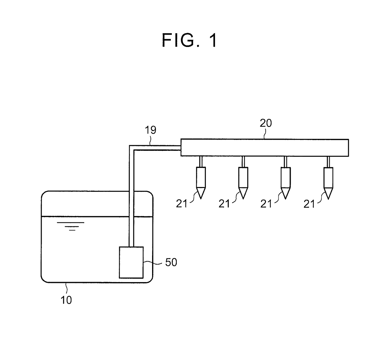
[0029]Hereinbelow, an embodiment as one example of a fuel pump will be described in detail with reference to FIGS. 1 to 6. A fuel pump 50 of this embodiment is configured as a high-pressure fuel pump that is disposed in an in-cylinder injection type engine for a vehicle.

[0030]As shown in FIG. 1, the fuel pump 50 that pumps out and pressurizes fuel is disposed in a fuel tank 10 of the in-cylinder injection type engine. The fuel pump 50 is connected to a delivery pipe 20 via a high-pressure fuel passage 19. Injectors 21 disposed in respective cylinders of the in-cylinder injection type engine are connected to the delivery pipe 20.

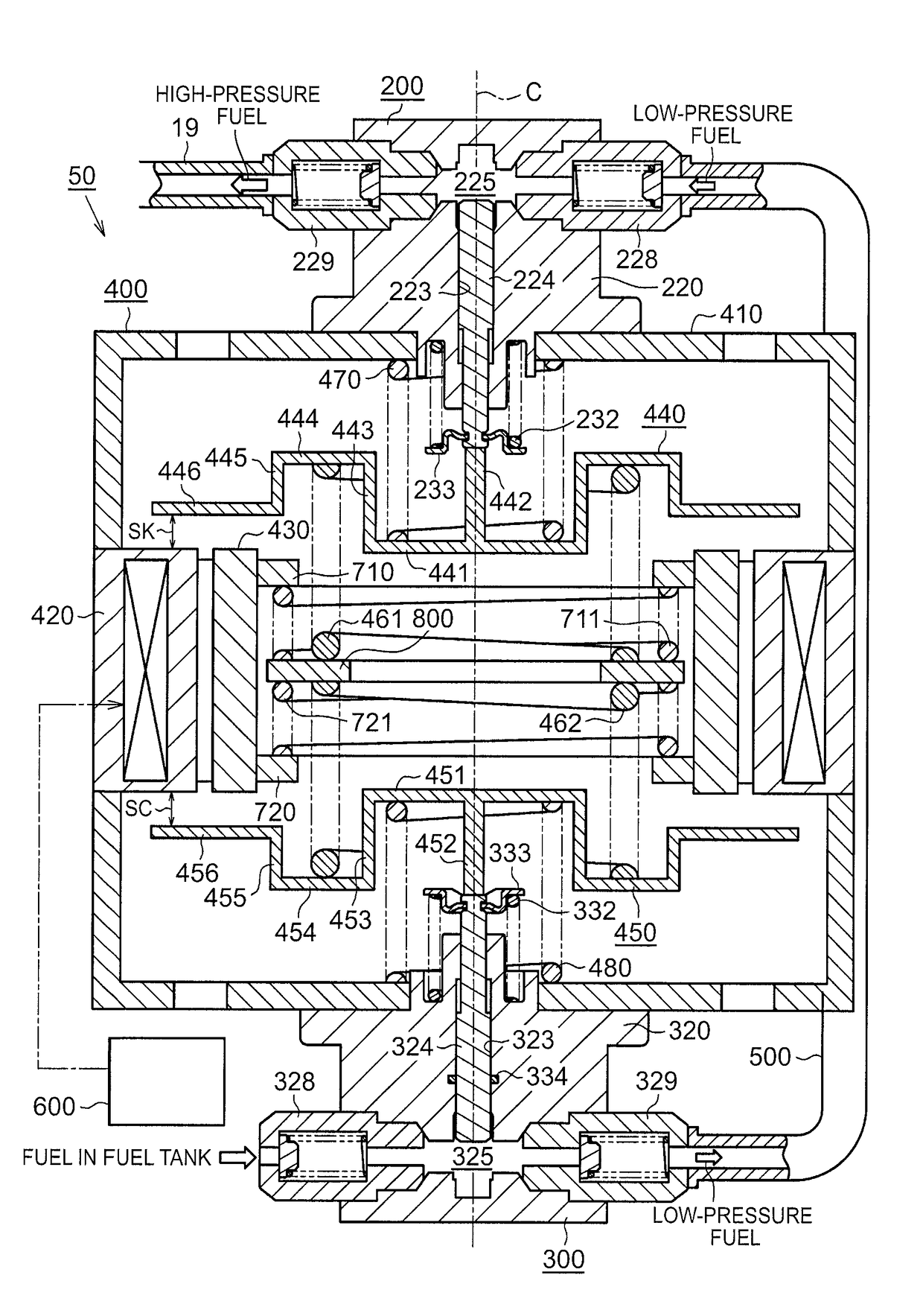
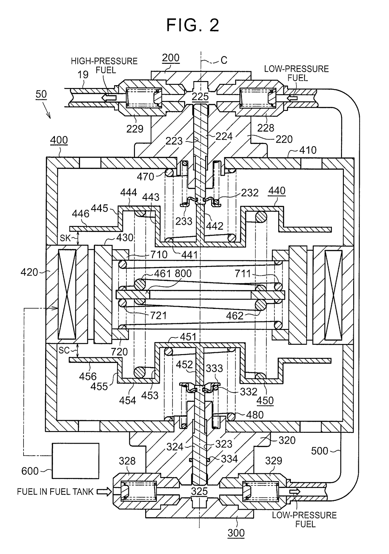
[0031]As shown in FIG. 2, the fuel pump 50 includes a first pump portion 200, a second pump portion 300, a drive portion 400, and a low-pressure fuel passage 500. The first pump portion 200 discharges high-pressure fuel. The second pump portion 300 discharges low-pressure fuel. The drive portion 400 drives the first pump portion 200 and the second pump portio...


PUM


Abstract

A fuel pump includes a first plunger that reciprocates in a first cylinder. The fuel pump further includes a first mover connected to the first plunger; a second mover that serves as a counterweight for suppressing vibration that occurs due to reciprocating movement of the first mover; an electromagnet and a magnetic member that are provided between the first mover and the second mover; a plate disposed between the first mover and the second mover; and a third spring and a fourth spring being a pair of springs sandwiching the plate between the third spring and the fourth spring, the third spring and the fourth spring having end portions connected to a housing.

Description

CROSS-REFERENCE TO RELATED APPLICATIONS[0001]This application claims priority to Japanese Patent Application No. 2015-198630 filed on Oct. 6, 2015, the entire contents of which are hereby incorporated by reference.BACKGROUND[0002]1. Technical Field[0003]The present disclosure relates to a fuel pump.[0004]2. Description of Related Art[0005]There is known a fuel pump that pressurizes fuel in a pressurizing chamber, defined by a cylinder and a plunger, by the movement of the plunger in the cylinder. As a drive mechanism for reciprocating such a plunger, a device described, for example, in Japanese Patent Application Publication No. 2014-117149 (JP 2014-117149 A) includes a mover that is reciprocated by an electromagnet, wherein a piston that serves as a plunger is connected to the mover.[0006]In the meantime, when the mover is reciprocated, vibration occurs due to the reciprocating movement of the mover. Therefore, if, in order to suppress such vibration, a counterweight with a mass eq...

Claims


Application Information

Patent Timeline
Patent Type & Authority Patents(United States)
IPC IPC(8): F04B17/04F04B53/00F04B17/03F04B11/00F04B1/02F02M37/08F02M37/04F04B9/06F04B19/22
CPCF04B9/06F02M37/043F02M37/08F04B53/001F04B11/0075F04B17/03F04B19/22F04B1/02F02M59/00F02M59/44F04B17/042F04B53/14
Inventor ASAYAMA, KAZUHIRO
Owner TOYOTA JIDOSHA KK
Why Eureka
Try Eureka