Magnetorheological actuator having a rotationally driven threaded spindle and clutch having an actuator

a technology of magnetic actuator and threaded spindle, which is applied in the direction of gearing, magnetic circuit rotating parts, magnetic circuit shape/form/construction, etc., can solve the problems of affecting the degree of efficiency, size, complexity and/or cost, and the inability to complete separation of the strands connected by the clutch, etc., to achieve high transmittable force, increase the conveying rate of an mrf/of, and high pressure

Inactive Publication Date: 2018-10-02
SCHAEFFLER TECH AG & CO KG
View PDF9 Cites 3 Cited by
  • Summary
  • Abstract
  • Description
  • Claims
  • Application Information

AI Technical Summary

Benefits of technology

[0014]A special advantage of the invention is that in one embodiment, it may take what has been a disadvantageous property of an MRF, namely what is known as sedimentation, and use it to its advantage. When the MRF is exposed to a magnetic field, the MRF solidifies. The strength of an MRF in a solidified state basically depends on the yield stress and the shear area. When a shear stress applied to the MRF exceeds the yield stress, the chains formed by the polarized particles of the MRF will break. Due to the continuing effect of the magnetic field, however, the chains will immediately reform especially in areas of lower shear stress. The invention may make use of this circumstance to generate a virtually unlimited axial actuating force of the actuator. If there is a way for the MRF carrier liquid that has been conveyed behind the thread to return to a region in front of the thread, (in a way similar to a separation of particles and carrier fluid due to sedimentation), a cushion of MRF particle chains that are created by the continuing effect of the magnetic field may be built up behind the thread. On this cushion, the thread may apply high transmittable forces. The effect that is used in this instance will be explained in more detail below.
[0015]Advantageous embodiments of the invention are claimed in the dependent claims and will be explained in more detail below.
[0016]The threaded spindle may be received in the chamber to be axially displaceable. It may in particular be mounted in bearings. For this purpose, it is advantageous if the axial length of the thread is shorter than the axial length of the chamber.
[0017]The thread, in particular thread tips of the thread, may contact an interior wall of the chamber in a sealing manner. In this case, the MRF needs a way to return from one side of the thread to the other (as viewed in a longitudinal direction) in order for the thread to rotate therein without too much resistance when the MRF is in a liquid state.
[0018]In one embodiment, there is a clearance, gap, or depression for instance in the shape of a groove or bore between the thread tips, i.e. the outer edges, the outer or nominal diameter of the thread, and an interior wall of the chamber. The outer diameter or nominal diameter of the thread may in particular be smaller than the diameter of the interior wall of the chamber. Such a clearance allows the MRF that has been conveyed to one side of the thread by the thread helixes to flow back to the opposite side of the thread as a result of the high pressure that is built up on the first side. A continued rotation of the thread in the liquid MRF is thus possible without too much resistance. The clearance may in particular be dimensioned to allow the carrier liquid of the magnetorheological fluid to pass through the gap in particular when the magnetorheological fluid solidifies as a result of a magnetic field acting thereon. In a particularly advantageous way, the return of the MRF or MRF carrier fluid from one side of the thread to the other may be implemented by axial passages provided in the threaded spindle, in particular in the thread and / or the thread flanks to create a flow connection or shortcut between contiguous thread sections.
[0019]It is advantageous if the thread is a multi-start thread, in particular a two-, three-, or four-up to six-start thread. Compared to a single-start thread, the use of multi-start threads may increase the conveying rate of an MRF / of the polarizable or polarized particles of the MRF, providing an actuator with short and quick response times as desired for a fast / quick operation of clutches or brakes. An additional or alternative option to improve the conveying rate of the thread is to provide varying thread slopes, in particular a non-linear slope. In front sections, i.e. at the beginning of the conveying path, the thread may have a steep slope, resulting in a high conveying rate, whereas in a rear section, in particular at the end of the thread, the thread may have a gentler slope, resulting in a reliable support of the last thread section on a particle cushion located behind the thread. A further additional or alternative option to improve the conveying rate of the thread is to provide an interior diameter of the thread that is different from, in particular smaller than, the diameter of the spindle core in a region outside the thread.

Problems solved by technology

Main disadvantages of the indicated systems when they are integrated in compact clutches are size, complexity, and / or costs.
In particular in fast-rotating applications, a disadvantage of known MRF clutches is that a complete separation as it is possible in conventional clutches of the strands that are connected by the clutch is impossible because there will always be residual friction in the clutch due to the MRF, a fact which is detrimental to the degree of efficiency.
Another disadvantage is that the centrifugal effect on the particles of the MRF may affect the torque behavior.

Method used


Image

  • Magnetorheological actuator having a rotationally driven threaded spindle and clutch having an actuator
  • Magnetorheological actuator having a rotationally driven threaded spindle and clutch having an actuator
  • Magnetorheological actuator having a rotationally driven threaded spindle and clutch having an actuator

Examples


Embodiment Construction

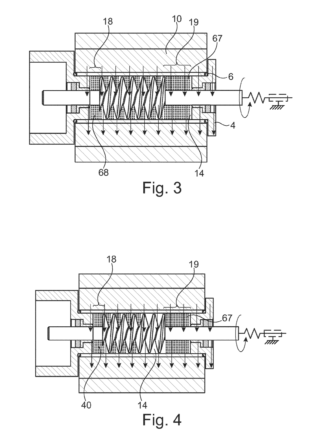
[0058]The figures are merely of a diagrammatic nature and are only provided for a better understanding of the invention. Identical elements have the same reference symbol. Details of the different embodiments may be combined with one another.

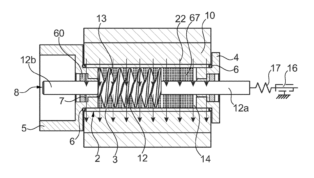
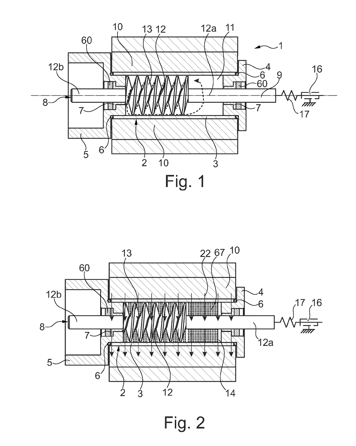
[0059]FIG. 1 is a diagrammatic representation of an embodiment of a magnetorheological actuator 1 of the invention. The actuator 1 has a housing 2 consisting of a tube 3 shaped like a hollow cylinder, a right-hand cover 4, and a left-hand cover 5. Covers 4, 5 may be screwed to the tube 3. The housing 2 is sealed between the tube 3 and the covers 4, 5 by means of a respective O-ring seal 6. A respective slide bearing 7 is inserted in a bearing opening formed in each cover 4, 5.

[0060]The slide bearings 7 are used to mount a threaded spindle 8 in the housing 2. The spindle 8 has a spindle core 12 and a thread 13 formed thereon. On both sides of the thread 13 there are spindle core 12 sections 12a 12b having a cylinder-shaped outer contour. By means...


PUM


Abstract

A magnetorheological actuator including a chamber, in particular a chamber at least sections of which are shaped like a hollow cylinder, containing a magnetorheological fluid, and further including a control element disposed in the chamber, wherein the control element suitable for applying the operating force of the actuator, wherein the control element is a threaded spindle or screw or threaded rod driven to rotate about its longitudinal axis, in particular about the screw axis, and including a spindle core and a thread disposed thereon, the thread surrounded by the magnetorheological fluid, is provided. A clutch having such an actuator is also provided.

Description

[0001]The invention relates to a magnetorheological actuator comprising a chamber, in particular a chamber at least sections of which are shaped essentially like a hollow cylinder, which contains a magnetorheological fluid, and further comprising a control element disposed in the chamber, the control element disposed to apply an operating force of the actuator.BACKGROUND[0002]Such actuators are used, for instance, in the field of motor vehicle technology for operating clutches in manual or automatic transmissions, dampers, or brakes etc. In manual transmissions, the actuator usually consists of a hydraulic system that is directly operated by the driver. A hydraulic section of a specific transmission ratio transmits the operating energy from a pedal that has been operated by the driver to a disengagement element of the clutch. In automatic transmissions or hybrid drive trains, there are a number of different operating devices or actuators that are implemented in the form of combinati...

Claims


Application Information

Patent Timeline
Patent Type & Authority Patents(United States)
IPC IPC(8): F16D29/00F16D27/115H02K7/08H02K5/02H02K7/11H02K1/22H02K99/00F16D121/18
CPCF16D29/00F16D27/115H02K1/22H02K7/08H02K7/11H02K99/20H02K5/02F16D2121/18F16D13/52F16D13/56F16D13/76F16D27/10F16D27/14F16D37/02F16D2023/123F16H25/24H02K7/116H02K1/246H02K19/103F16D28/00
Inventor BERTHELEMY, PIERRE-YVES
Owner SCHAEFFLER TECH AG & CO KG
Why Eureka
Try Eureka