Interactive spatial orientation method and system

a spatial orientation and spatial orientation technology, applied in the field of spatial orientation, can solve the problems of limiting application and poor ability to take real-time measurements

Active Publication Date: 2018-10-02
VR TECH (SHENZHEN) LTD
View PDF5 Cites 0 Cited by
  • Summary
  • Abstract
  • Description
  • Claims
  • Application Information

AI Technical Summary

Benefits of technology

[0048]Compared with the prior art, the invention simplifies the calculation by scanning along the longitude direction and the latitude direction respectively and sequentially, and the number of measuring instruments is reduced and the structure becomes simpler. A lot of scanning time is saved by the nonlinear scanning method. Scanning instruments can skip some area where the target cannot exist and focus on the scanning of the area where the target may exist, which greatly improves the efficiency of scanning and real-time performance of the spatial orientation. The mass of the rotating body becomes small by using the rotating polyhedron 141, the scanning galvanometer 142 and the microelectromechanical mirror 143, which is helpful in reducing a centrifugal force generated by the rotation or the vibration and increasing the stability of the equipment. The quantity of the rotating body is reduced to 1 by using the 2D controllable microelectromechanical mirror 144, which further simplifies the device. The periodic flash of the flash light allows the system to better determine the scan cycle and prevents data confusion between different periods. The exit light processing module 17 can increase or decrease the exit angle of the exit laser, and enlarge the range of the scanning.

Problems solved by technology

This kind of spatial orientation system tends to consist of large measuring equipments, and have long measurement time and poor capability of real-time measurements, thus substantially limiting the application.

Method used


Image

  • Interactive spatial orientation method and system
  • Interactive spatial orientation method and system
  • Interactive spatial orientation method and system

Examples


Embodiment Construction

[0032]The present application provides an interactive spatial orientation method and system with simple equipments and shorter measuring time, aiming at the drawback of the current spatial orientation with miscellaneous equipment and long measuring time.

[0033]To make the technical feature, objective and effect of the present application be understood more clearly, now the specific implementation of the present application is described in detail with reference to the accompanying drawings and embodiments.

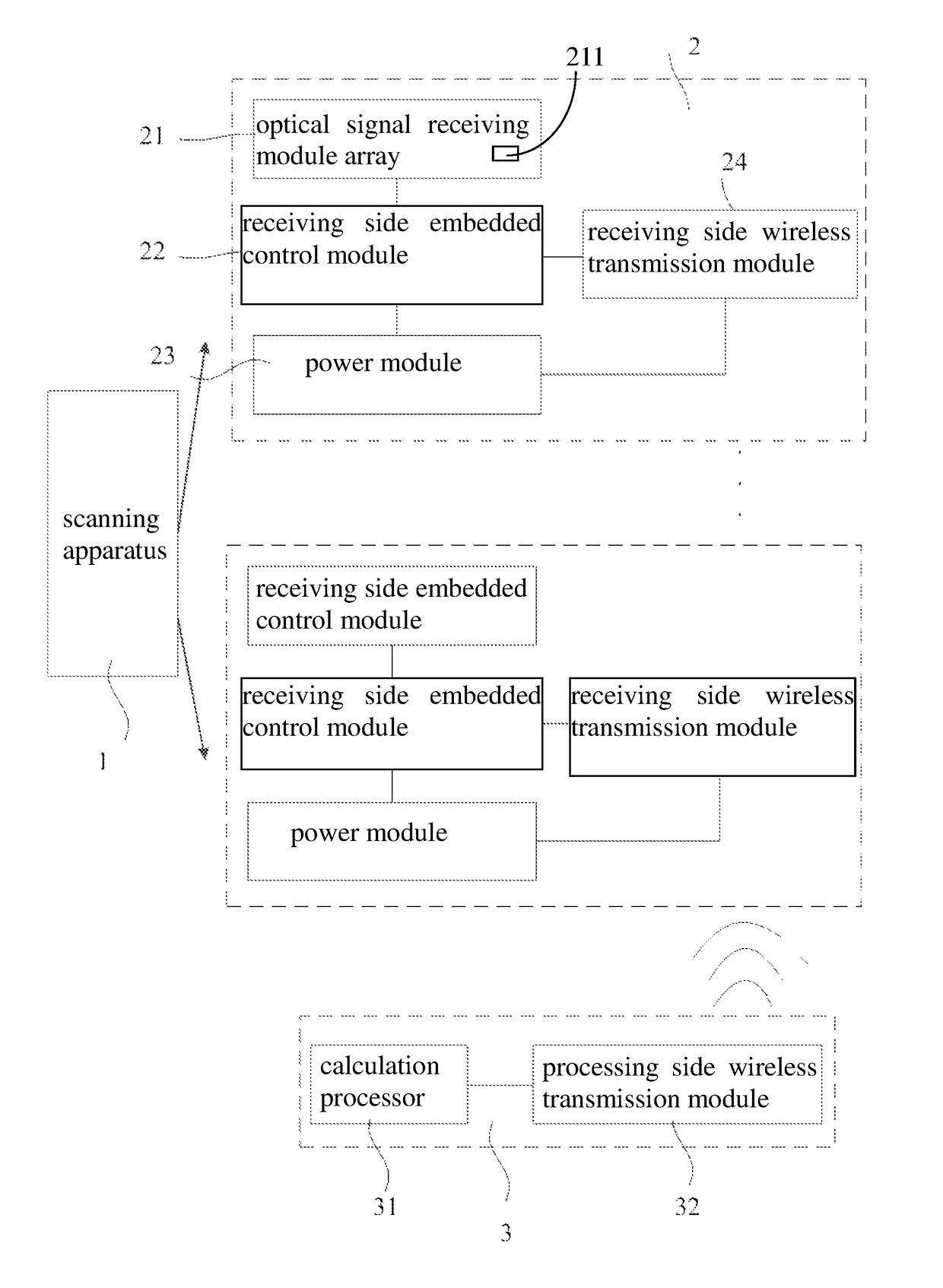
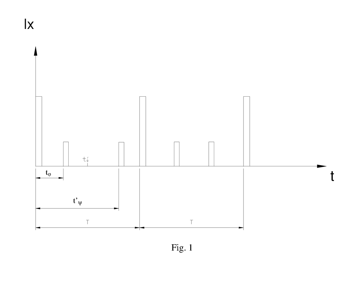
[0034]FIG. 1 is a schematic diagram of the interactive spatial orientation method and system according to the present application. In the axes, the horizontal axis represents the time t, and the vertical axis represents the light intensity 1×. When the measurement is started, a flash signal is given, and the receiving apparatus receives an optical signal with a light intensity that is far greater than or far less than the light intensity of the measured laser. The flash signal is mai...


PUM


Abstract

Disclosed is an interactive spatial orientation method and system. The method includes: sequentially scanning, by a scanning apparatus, a receiving apparatus in a first direction and a second direction perpendicular to each other; converting, by the receiving apparatus, received optical signals generated from the first scanning and the second scanning into radio waves carrying results of the first scanning and the second scanning, and transferring the radio waves to a processing apparatus; synthesizing, by the processing apparatus, the results of the first scanning and the second scanning to obtain six degrees of freedom information of the receiving apparatus. The system includes a scanning apparatus; a receiving apparatus; and a processing apparatus.

Description

CROSS REFERENCE TO RELATED APPLICATIONS[0001]The present application claims the benefit of Chinese Patent Application No. 201610281117.0 filed on Apr. 29, 2016. All the above are hereby incorporated by reference.TECHNICAL FIELD[0002]The present application relates to the field of spatial orientation, and more particularly relates to an interactive spatial orientation method and system.BACKGROUND OF THE APPLICATION[0003]Spatial orientation generally uses an optical or ultrasonic mode for positioning and measuring, and derives the spatial position of an object to be measured by building models. A general optical spatial orientation system determines the spatial position of an object by using a laser for scanning and a light sensor for receiving. This kind of spatial orientation system tends to consist of large measuring equipments, and have long measurement time and poor capability of real-time measurements, thus substantially limiting the application.SUMMARY OF THE APPLICATION[0004]T...

Claims


Application Information

Patent Timeline
Patent Type & Authority Patents(United States)
IPC IPC(8): G01B11/14G01B11/00G01B11/02G01S5/16
CPCG01B11/002G01S5/16G01B11/14G01B11/026G01S5/02G02B26/105G01S5/163G01C15/002
Inventor DANG, SHAOJUN
Owner VR TECH (SHENZHEN) LTD
Why Eureka
Try Eureka