
Flight control system with low-frequency instrument landing system localizer anomaly detection and method of use

a control system and low-frequency instrument technology, applied in the field of flight control systems, can solve problems such as misguiding the aircraft, increasing the likelihood of disruption of localizer signals transmitted from the ground,

Active Publication Date: 2018-10-02
THE BOEING CO
View PDF38 Cites 2 Cited by
  • Summary
  • Abstract
  • Description
  • Claims
  • Application Information

AI Technical Summary

Benefits of technology

The present patent provides a flight control module and system for detecting anomalies in the localizer signals of an aircraft during landing. The module receives inertial data and GPS position data and computes an inertial localizer deviation and a GPS localizer deviation. The system detects a low-frequency anomaly in the localizer signals and initiates a transition from controlling the aircraft based on the localizer signals to controlling it based on the inertial data. This allows for safer and more accurate landing of the aircraft.

Problems solved by technology

More frequent use of automated landing systems under VFR conditions increases the likelihood of disruptions in the localizer signals transmitted from the ground.
Anomalies may result in drifting of the localizer input to automated landing systems, which may further result in misguiding the aircraft during landing and ultimately transitioning from automated landing to a manual landing.

Method used


Image

  • Flight control system with low-frequency instrument landing system localizer anomaly detection and method of use
  • Flight control system with low-frequency instrument landing system localizer anomaly detection and method of use
  • Flight control system with low-frequency instrument landing system localizer anomaly detection and method of use

Examples


Embodiment Construction

[0016]As used herein, an element or step recited in the singular and proceeded with the word “a” or “an” should be understood as not excluding plural elements or steps unless such exclusion is explicitly recited. Furthermore, references to “one embodiment” of the present invention or the “exemplary embodiment” are not intended to be interpreted as excluding the existence of additional embodiments that also incorporate the recited features.

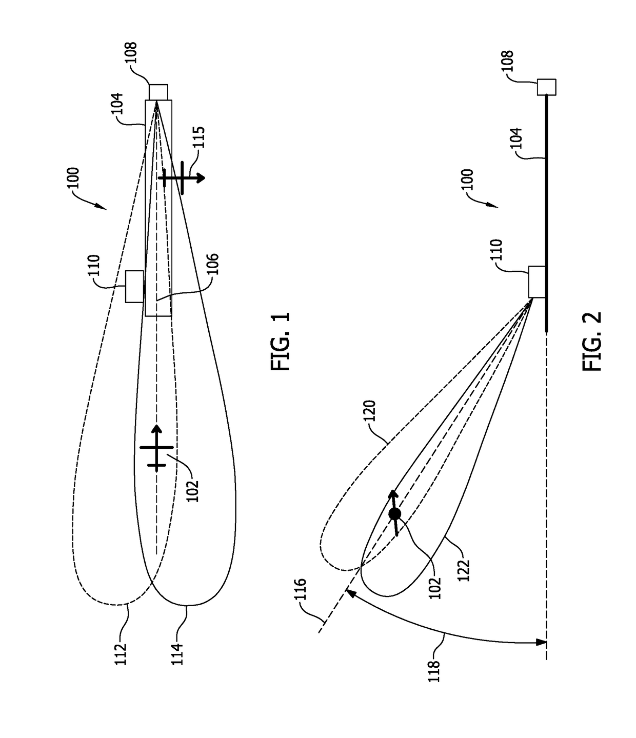
[0017]FIG. 1 is a perspective diagram, from a top-view, of an exemplary instrument landing system (ILS) 100 for use in landing an aircraft 102. FIG. 2 is another perspective diagram, from a side view, of ILS 100. Aircraft 102 is illustrated during approach for landing on a runway 104. Runway 104 is characterized by a runway centerline 106 that extends towards and beyond aircraft 102 for illustrative purposes.

[0018]Referring to FIG. 1, in the exemplary embodiment, ILS 100 includes a localizer transmitter 108 and a glideslope transmitter 110. Localiz...


PUM


Abstract

A flight control module for detecting anomalies in ILS localizer signals during landing of an aircraft is provided. The flight control module includes a communication interface and a processor coupled thereto. The communication interface is configured to receive inertial data, GPS data, and an ILS localizer deviation for the aircraft. The processor is configured to compute an inertial localizer deviation based on the inertial data and a GPS localizer deviation based on the GPS data. The processor is configured to compare the ILS localizer deviation to an average of the inertial localizer deviation and the GPS localizer deviation to detect a low-frequency anomaly in the ILS localizer deviation. The processor is configured to initiate a transition from controlling the aircraft based on the ILS localizer deviation to controlling the aircraft based on the inertial localizer deviation when the low-frequency anomaly is detected.

Description

BACKGROUND[0001]The field of the disclosure relates generally to flight control systems and, more specifically, to a flight control module utilizing a synthetic inertial localizer deviation for detecting low-frequency instrument landing system (ILS) localizer anomalies.[0002]Many known aircraft feature an automated landing system that controls the aircraft during landing. Automated landing systems have become increasingly more common and are frequently relied on for both instrument landings under instrument flight rules (IFR) and landings performed under visual flight rules (VFR). Known automated landing systems utilize various receivers, such as multi-mode receivers (MMRs), for example, to receive guidance signals transmitted from the ground. Such guidance signals may include, for example, ILS signals, global positioning service (GPS) landing system (GLS) signals, and / or microwave landing system (MLS) signals. The guidance signals inform the aircraft of its position relative to a d...

Claims


Application Information

Patent Timeline
Patent Type & Authority Patents(United States)
IPC IPC(8): G06F19/00G06G7/70G08G5/02G05D1/02G05D1/06B64D45/04
CPCG08G5/025G05D1/0202G08G5/02G05D1/0676B64D45/04G01S19/48G01S19/49G05D1/101G01S13/882G01S19/15
Inventor MCLEES, ROBERT E.HOOKS, ANDREW R.PANYAKEOW, PRACHYA
Owner THE BOEING CO
Learn More