Vision based real-time object tracking system for robotic gimbal control

a real-time object and robotic gimbal technology, applied in the direction of television systems, direction/deviation determining electromagnetic systems, instruments, etc., can solve the problems of gps multipath errors, camerapersons need a level of expertise, and it is difficult to follow and capture a shot of the subject target, so as to achieve better accuracy and reliability

Active Publication Date: 2018-10-09
REFLEX ROBOTICS
View PDF4 Cites 167 Cited by
  • Summary
  • Abstract
  • Description
  • Claims
  • Application Information

AI Technical Summary

Benefits of technology

[0005]The innovative subject matter described herein discloses methods, systems, and devices that are able to control a pivoting device (e.g., gimbal) operating with varying degrees of freedom. Such methods, systems, and devices can be used to track a subject target within a three dimensional space to capture desired movements or angles of the subject target. Such methods, systems, and devices can track a subject target within a three dimensional space with better accuracy and reliability.
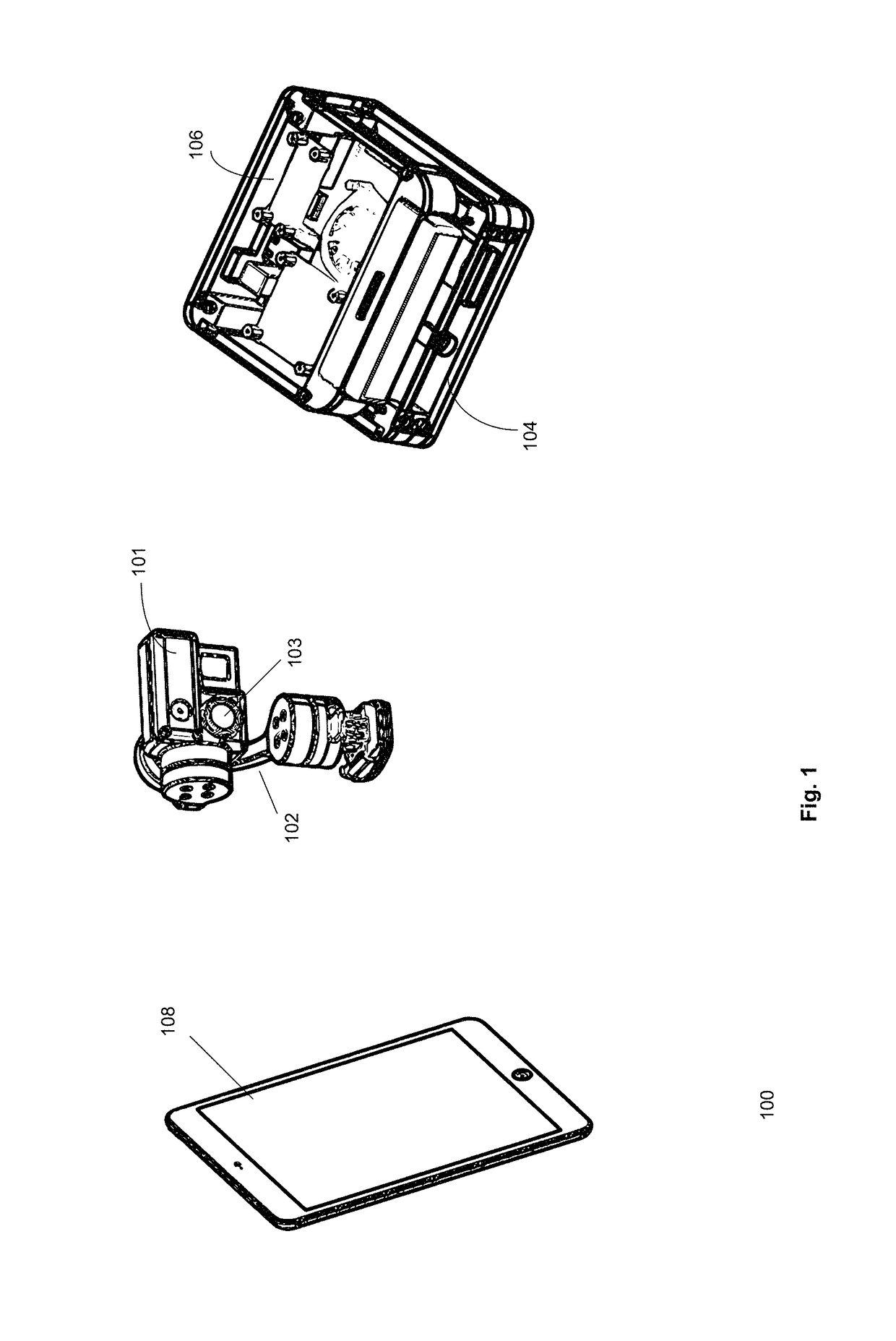
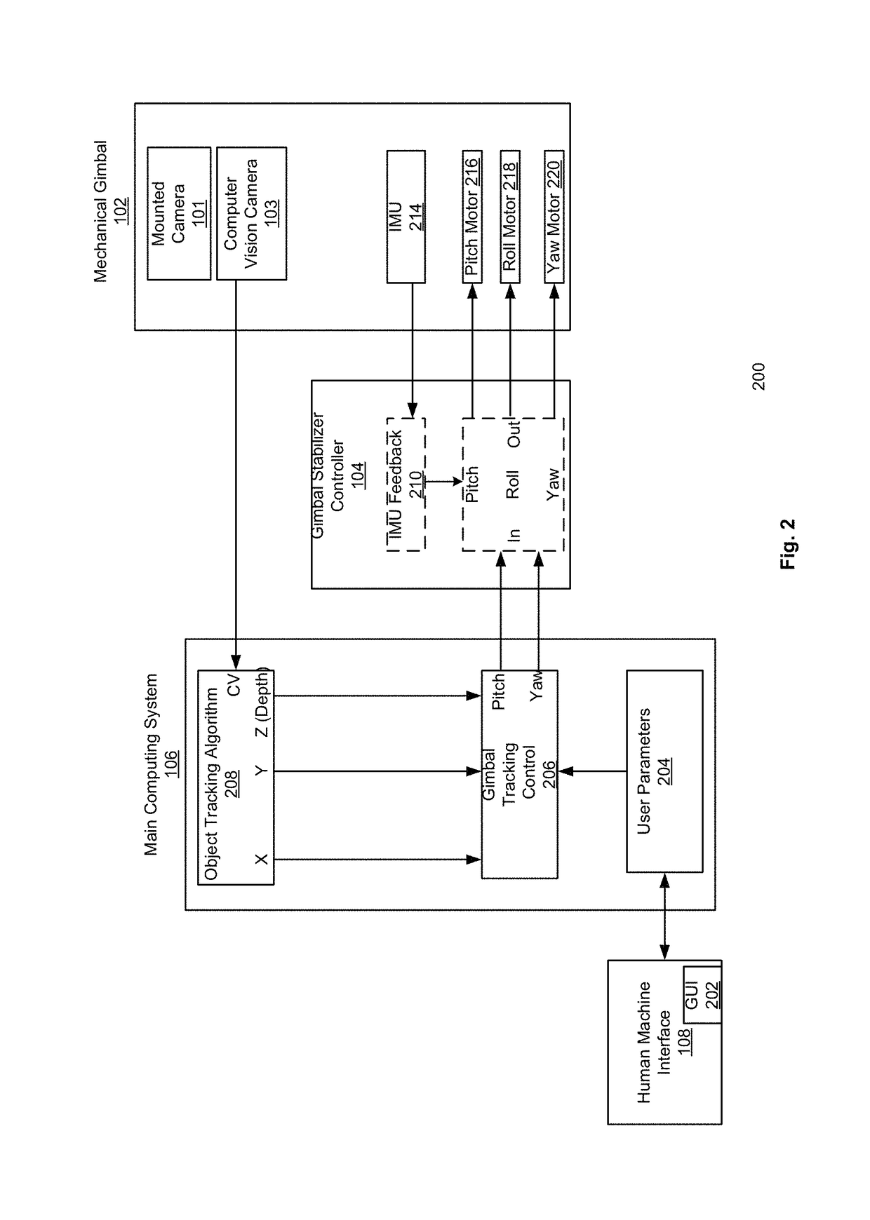
[0008]In one embodiment, the main computing system and gimbal stabilizer controller, together, are at least included in the pivoting device control system, described herein. The system is capable of controlling the movements of the pivoting device, thereby controlling the movement of the user's camera that is mounted on the pivoting device (adjustments made to the pivoting device can adjust the direction and angle(s) of the user's camera). The main computing system and gimbal stabilizer of such a system can be integrated together as a single computing device or can be in separate devices. In one embodiment, once the system initializes, a user can select a subject target (also referred to as a target object herein) using a machine interface (e.g., a computer input output peripheral such as a tablet, mouse, pointer device, keyboard, etc.); the user can select a subject target, i.e., an object to track, such as a snowboarder, another car, etc., to begin tracking the object or person. The user can select fixed shaped objects (e.g., car) or non-rigid objects (e.g., human, animal, etc.). Once the system is initialized the user can then start recording or capturing photographic images of the subject target. As the subject target moves (and the user begins following the subject target) the system can automatically adjust the position (e.g., orientation) of the camera using the pivoting device (e.g., gimbal, in one embodiment). Also, any unwanted movements of the pivoting device or gimbal (e.g., tilt, pan, and roll movements) can be stabilized by the system thereby resulting in a clear and focused shot of the subject.
[0015]Thus, in embodiments capable of detecting rigid or non-rigid objects, the use of markers, tags, or beacons can be optional to provide redundancy and / or greater accuracy. The vision based algorithms used in any such embodiment can be based on tracking an object by detection with increased adaptability by comparing the current frame to the prior frame(s). In one embodiment, the system can learn general features from the object (e.g., an outline of the object, the location of different colors on the object, etc., or a combination thereof). The system can also adapt through the use of machine learning by analyzing most recent frames with the previous frames in order to adapt to the changes in a non-rigid object. Thus, the system can maintain detection and tracking of the object even if the object moves or changes shape. In another embodiment, statistical analysis through the use of estimators (e.g., Kalman filters), can be implemented to predict object trajectories in order to avoid breaks or jerky movements in the tracking of the subject target, or when the object being tracked (interchangeably referred to as the subject target or object target through out the disclosure, herein) is out of view (e.g., behind a tree, structure, etc.).

Problems solved by technology

However, in dynamic environments, conditions, and activities (e.g., extreme sports, capturing shots of wild or rouge animals, aerial law enforcement chasing an alleged law violator, journalists capturing a news worthy event, etc.), following and capturing a shot of the subject target can be difficult.
Furthermore, such camerapersons need a level of expertise and can usually only be afforded by professionals.
Furthermore, such a system is dependent on the GPS unit's limited ability to transmit its location in a two dimensional space, that is clear from major obstructions (e.g., tall buildings) which may cause GPS multipath errors.

Method used


Image

  • Vision based real-time object tracking system for robotic gimbal control
  • Vision based real-time object tracking system for robotic gimbal control
  • Vision based real-time object tracking system for robotic gimbal control

Examples


Embodiment Construction

[0043]Various embodiments and aspects of the inventions will be described with reference to details discussed below, and the accompanying drawings will illustrate the various embodiments. The following description and drawings are illustrative of the invention and are not to be construed as limiting the invention. Numerous specific details are described to provide a thorough understanding of various embodiments of the present invention. However, in certain instances, well-known or conventional details are not described in order to provide a concise discussion of embodiments of the present inventions.

[0044]Reference in the specification to “one embodiment” or “an embodiment” or “another embodiment” means that a particular feature, structure, or characteristic described in conjunction with the embodiment can be included in at least one embodiment of the invention. The appearances of the phrase “in one embodiment” in various places in the specification do not necessarily all refer to t...


PUM


Abstract

Using various embodiments, methods, systems, and apparatuses for controlling a camera pivoting device (e.g., mechanical gimbal) are described. In one embodiment, the system comprises a main computing device, a gimbal stabilizer controller, and a computer vision camera, and / or a user camera. The system is able to track a target object using the computer vision camera even while the target object is moving, the base of the pivoting device is moving (e.g., when a user controlling the camera moves), or a combination of thereof. The camera pivoting device of the embodiments disclosed herein can be mounted on to any number of devices / objects that can provide mobility and / or transportation.

Description

CROSS REFERENCE TO RELATED APPLICATIONS[0001]The present application claims priority from U.S. Provisional Patent Application No. 62 / 092,097 filed on Dec. 15, 2014, titled “PIVOTING DEVICE CONTROL,” under 35 U.S.C. 119(e). The contents of the above mentioned provisional patent application is incorporated herein by reference for all purposes to the extent that such subject matter is not inconsistent herewith.FIELD OF THE INVENTION[0002]Embodiments of the present invention relates generally to automatic tracking of object(s) using a camera. More particularly, embodiments of the invention relates to tracking objects by automatically controlling the movements of a pivoting device on to which a camera is mounted while the camera and / or the object being tracked are physically moving within a three dimensional space.BACKGROUND OF THE INVENTION[0003]Photography and videography requires a cameraperson to capture a shot of the subject target. However, in dynamic environments, conditions, and ...

Claims


Application Information

Patent Timeline
Patent Type & Authority Patents(United States)
IPC IPC(8): G06K9/32H04N5/232G06T7/20G01S3/786G06V10/25
CPCG06K9/3233G06T7/20G01S3/7864H04N5/2328G06V10/25H04N23/685
Inventor MENTESE, ENESKIM, SEONGDOBABUKR, ABDO
Owner REFLEX ROBOTICS
Why Eureka
Try Eureka