
Broken line repair method of TFT substrate

a technology of tft substrate and broken line, which is applied in the field of display technology, can solve the problems of poor quality of liquid crystal display with broken lines, waste of liquid crystal display, and the inability to reduce the line ratio to be 0 , to achieve the effect of reducing the risk of broken lines, promoting the adhesion result and uniformity of metal growing film, and raising the success ratio of broken line on the substra

Active Publication Date: 2018-10-16
TCL CHINA STAR OPTOELECTRONICS TECH CO LTD
View PDF8 Cites 0 Cited by
  • Summary
  • Abstract
  • Description
  • Claims
  • Application Information

AI Technical Summary

Benefits of technology

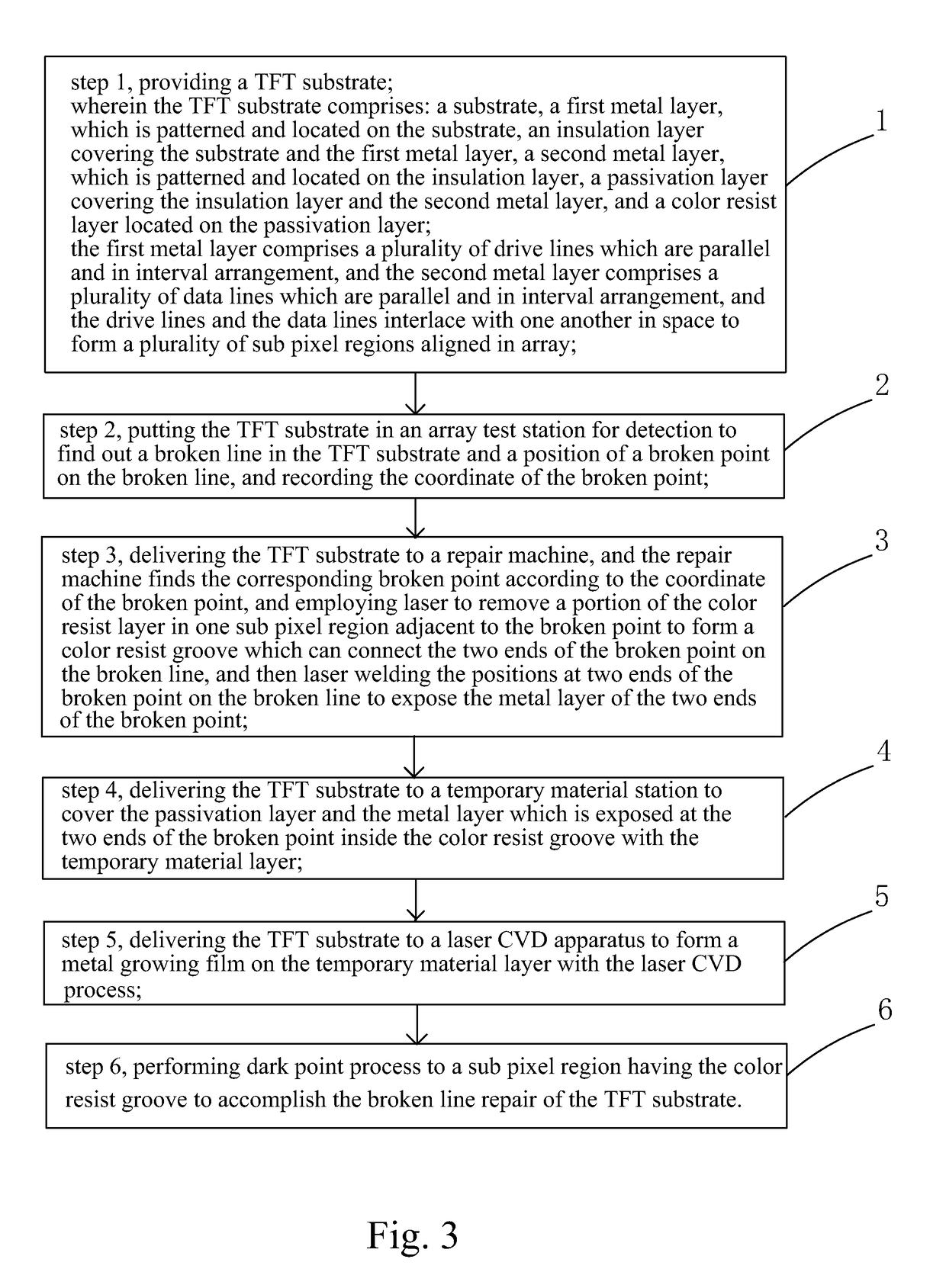
The present invention provides a method for repairing broken lines on a TFT substrate. The method involves finding the location of the broken line, processing the passivation layer to expose a metal layer, covering the substrate with a temporary material layer, and forming a metal growing film to connect the broken lines. This method improves the adhesion and uniformity of the metal growing film, reduces the risk of broken lines and peeling off, and increases the success rate of repairing the TFT substrate.

Problems solved by technology

Because the broken line appears due to the process defect of the TFT substrate, the broken line ratio can never be decreased to be 0 by improving the production process, which is the inevitable defect in the liquid crystal display.
The quality of the liquid crystal display with the broken line is poor.
Once the broken line is found in the procedure of shipping out, the liquid crystal display has to be wasted, and the production cost increases.
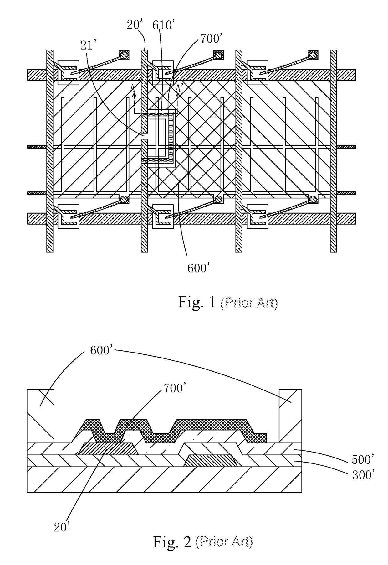
When this repair method of broken line performs color resist remove, if the energy of removing the color resist is too small, the color resist remains on the passivation layer 500′, and if the energy of removing the color resist is too large, the folding is formed on the passivation layer 500′, which ultimately result in the local small of the metal growing film 700′ and the poor adhesion result of the metal growing film 700′ and the passivation layer 500′.
It can easily cause the risk of broken line and Peeling to the metal growing film 700′ and reduce the success ratio of the TFT broken line repair.

Method used


Image

  • Broken line repair method of TFT substrate
  • Broken line repair method of TFT substrate
  • Broken line repair method of TFT substrate

Examples


Embodiment Construction

[0053]For better explaining the technical solution and the effect of the present invention, the present invention will be further described in detail with the accompanying drawings and the specific embodiments.

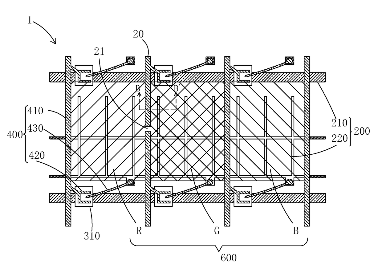
[0054]Please refer to FIG. 14 combining FIG. 3, the present invention provides a broken line repair method of a TFT substrate. When the method is applied to repair the broken line in the display region of the TFT substrate, the method comprises steps of:

[0055]step 1, referring to FIG. 4 and FIG. 5, providing a TFT substrate 1 in which a broken line is to be repaired.

[0056]Specifically, the TFT substrate 1 comprises: a substrate 100, a first metal layer 200, which is patterned and located on the substrate 100, a gate insulation layer 300 covering the substrate 100 and the first metal layer 200, a second metal layer 400, which is patterned and located on the gate insulation layer 300, a passivation layer 500 covering the gate insulation layer 300 and the second metal layer 400, ...


PUM

PropertyMeasurementUnit
colorsaaaaaaaaaa
adhesionaaaaaaaaaa
structure diagramaaaaaaaaaa

Abstract

The present invention provides a broken line repair method of a TFT substrate. The method first finds out a broken line in the TFT substrate and a position of a broken point on the broken line. Then, positions of the passivation layer intersecting with the broken line at two ends of the broken point are processed, respectively to expose a metal layer, where the broken line is. Then, a temporary material layer is covered on the passivation layer and the metal layer which is exposed at the two ends of the broken point. Finally, a metal growing film is formed on the temporary material layer to connect the broken line of the two ends of the broken point. With the temporary material layer, the issue of bad repair result due to the remain of the color resist layer and the folding of the passivation layer can be solved.

Description

FIELD OF THE INVENTION[0001]The present invention relates to a display technology field, and more particularly to a broken line repair method of a TFT substrate.BACKGROUND OF THE INVENTION[0002]The Liquid Crystal Display (LCD) is one of the most widely utilized flat panel displays, and the liquid crystal display panel is the core component of the Liquid Crystal Display.[0003]The traditional liquid crystal panel generally comprises a Color Filter (CF), a Thin Film Transistor Array Substrate (TFT Array Substrate) and a Liquid Crystal Layer positioned inbetween. The working principle is that the liquid crystal molecules are positioned between the two parallel glass substrates, and many vertical and horizontal tiny little electrical lines are between the two glass substrates, and the light of backlight module is reflected to generate images by applying driving voltages or not for controlling the direction changes of the liquid crystal molecules. The thin film transistor (TFT) array manu...

Claims


Application Information

Patent Timeline
Patent Type & Authority Patents(United States)
IPC IPC(8): G02F1/13G02F1/1368H01L21/768H01L21/786H01L21/82H01L27/12G02F1/1362
CPCG02F1/1309G02F1/1368G02F1/136259H01L21/786H01L21/82H01L27/12H01L21/768G02F2001/136263G02F1/136263H01L21/76892H01L22/14H01L22/20H01L27/124
Inventor ZHAO, HEXIE, KECHENG
Owner TCL CHINA STAR OPTOELECTRONICS TECH CO LTD
Learn More