Inferior vena cava filter with stability features

a technology of stability features and inferior vena cava, which is applied in the field of filter devices, can solve the problems of difficult atraumatic removal of filters, and achieve the effect of easy removal

Active Publication Date: 2018-10-23
CR BARD INC
View PDF30 Cites 1 Cited by
  • Summary
  • Abstract
  • Description
  • Claims
  • Application Information

AI Technical Summary

Benefits of technology

[0019]According to the exemplary embodiments, there is provided, a vessel-implantable filter of shape memory material with temperature induced austenitic and martensite states which may be easily removed by a single removal device after an extended period of time without significantly injuring the vessel wall. In the exemplary embodiments, the filter is of shape memory material which operates in a temperature induced austenitic state to exert a force on the wall of a vessel by means of oppositely disposed second extension elements to maintain the filter in place, but which may easily be removed after the endothelium layer has covered the ends of the filter second extension elements without significant damage to the vessel wall.
[0021]Preferably, the hooks are elastic and formed on the free end of an appendage to pierce the vessel wall and insure that the filter remains stable even in response to movement, such as respiratory functions or in the event of a massive pulmonary embolism. The hook is formed to have a maximum migration force, and when subjected to forces below the maximum migration force, the hook retains its shape. When subjected to forces above the maximum migration force, the hook straightens and can automatically disengage without significant damage to the vessel wall.
[0024]In a preferred variation of the foregoing embodiment, the appendages are arrayed in two circular arrays which are offset or spaced along the axial direction. In this case, the appendages at one end may be referred to as second extension elements and the appendages at the other end may be referred to as first extension elements. More preferably, both the first extension elements and the second extension elements have features at their extreme ends which are designed to engage the wall of a vena cava in such a way as to resist axial force. Preferably, the total force the appendages / tips can resist is no more than that required to resist blood flow pressure of 50 mm Hg over the cross-sectional area of the vessel. By providing some support from the first extension elements as well as the second extension elements, the total force per axial-load-resisting contact point is reduced. For example, if the tips are sharp and penetrate the vessel wall, the load per vessel-wall penetration is thereby reduced, causing reduced risk of trauma, particularly upon withdrawal of the filter.
[0026]Preferably, the second surfaces are more effective to prevent upstream movement than to prevent downstream movement. Preferably, each of the second surfaces defines a sharp tip that is angled such that the tip tends to withdraw from the vessel wall if the second portion of the wall-contacting elements is moved in the downstream direction. Preferably, the second portion of the wall-contacting elements are configured to buckle, thereby changing the angles of the sharp tips such that the sharp tips tend to withdraw from the vessel wall on upstream movement. Also, in a variant embodiment, the second portion of the wall-contacting elements are configured to buckle when the filter moves in an upstream direction. Also, in another variant embodiment, the wall contacting surfaces of the first and second portion of the wall-contacting members are axially displaced relative to each other to serve to orient the filter in the blood vessel. In yet another a variant embodiment, the first portion of the wall-contacting members have respective weakened portions that are shaped to limit the amount of radial force the first surfaces apply to the vessel wall.
[0032]According to an embodiment, a blood clot filter has a hub extending in a hub direction from a first hub end to a second hub end along a longitudinal axis. A plurality of second extension elements extend away from the second hub end along the longitudinal axis, each of the second extension elements having a second extension element end proximate the hub and a hook at or near a distal end of the second extension element to retain the second extension element to a blood vessel wall. A plurality of first extension elements extend away from the second hub end along the longitudinal axis. Each of the first extension elements has a first end and free end, the first end of each first extension element preferably being contiguous with a portion of the second extension element. In addition, the free end of each first extension element is preferably closer to the axis of the filter than the hook of each second extension element. Moreover, the free ends of each of the first extension elements are preferably spaced equiradially from the longitudinal axis. At least some of the first extension element free ends have features to engage the vessel inner wall to promote stability of the filter.
[0034]According to an embodiment, a blood clot filter has a hub extending in an axial direction with radially extending elements having vessel wall-engaging ends. First radially extending elements have first wall-engaging ends configured to engage a vessel interior wall and thereby prevent downstream movement of the filter. Second radially extending elements having second wall-engaging ends configured to engage a vessel interior wall and thereby prevent upstream movement of the filter. The second radially extending elements are preferably configured to bend more easily in a first direction than a second.

Problems solved by technology

There are a number of conflicting issues concerning the design of vena cava filters.
Also, the design features that hold the filter in place must also not promote tissue growth that would make it difficult to remove the filter atraumatically.

Method used


Image

  • Inferior vena cava filter with stability features
  • Inferior vena cava filter with stability features
  • Inferior vena cava filter with stability features

Examples


Embodiment Construction

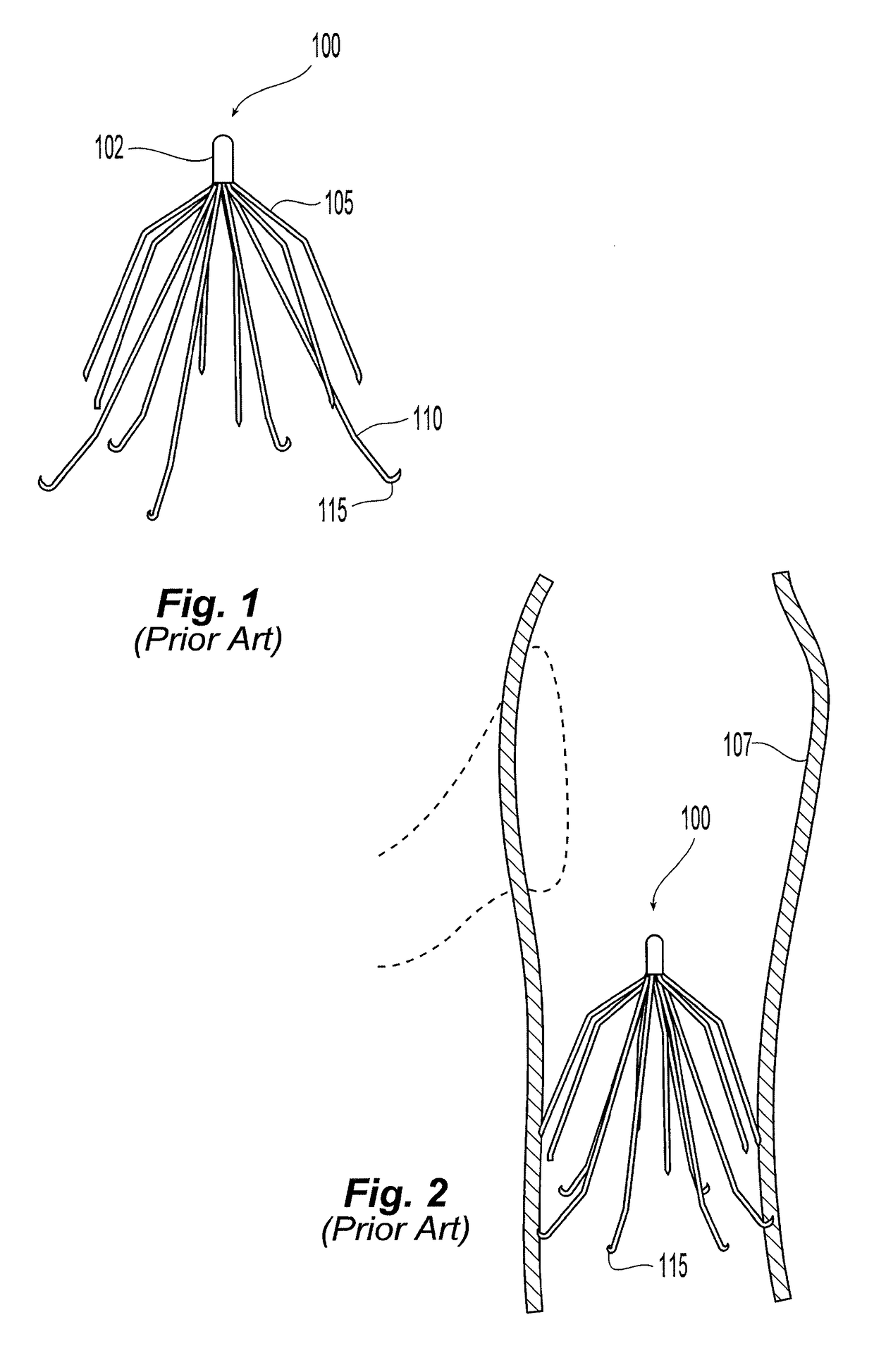
[0050]Referring to FIGS. 1 and 2, the filter 100 is shown in an expanded state. Preferably, the filter is made of metal wires held together by a hub where they are joined, for example, by plasma welding. The wires are preferably made of shape memory alloy with a martensite phase that allows the wires to be straightened so as to enable insertion in a catheter and deployment therefrom. In the austenitic phase, the filter recovers to its expanded state, which is illustrated.

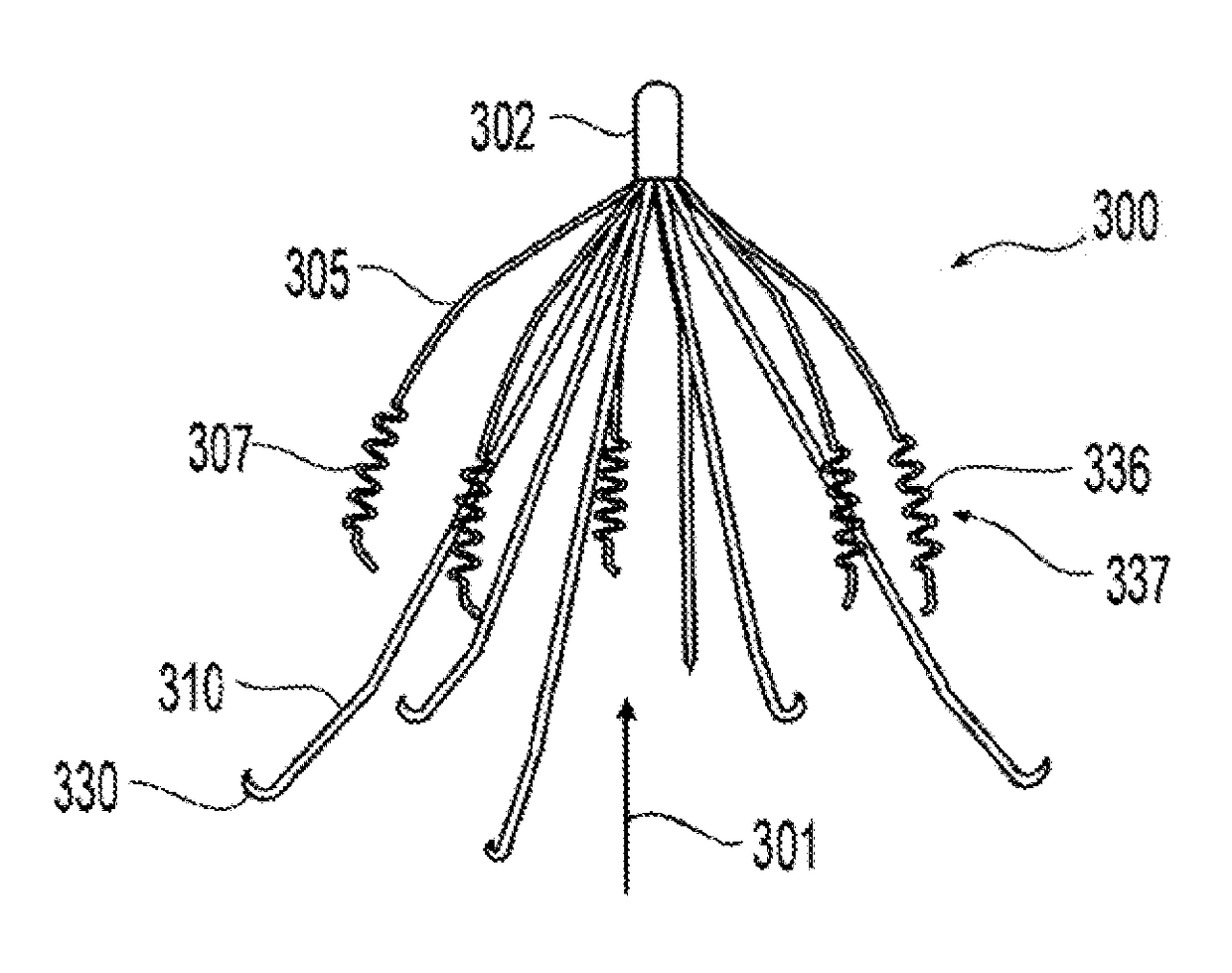
[0051]The filter 100 has a double basket or trap design with first extension elements 105 forming one basket or trap and second extension elements 110 forming a second basket or trap. Each of the extension elements 105, 110 have one end substantially centrally interconnected at the longitudinal axis of the filter 100 and a remote or distal end that extends radially away from the longitudinal axis. Alternatively or in addition to, where the centrally interconnected ends of the extensions elements 105, 110 are axially...


PUM


Abstract

A filter having a first set of members and a second set of members defining a trap sized to fit into a blood vessel. Each of the first and second members are configured to resiliently extend from the trap. At least one of the first set of members includes a first surface for engaging the vessel wall such that the at least one of the first set of members resists downstream movement within the vessel. At least one of the second set of members includes a second surface for engaging the vessel wall such that the at least one second member resists upstream movement within the vessel.

Description

PRIORITY DATA AND INCORPORATION BY REFERENCE[0001]This application claims the benefit of priority to U.S. Provisional Patent Application No. 60 / 870,722 filed Dec. 19, 2006, which is incorporated by reference in its entirety.TECHNICAL FIELD[0002]The invention relates to a filter device that can be placed via a catheter delivery system in a vessel of a mammalian body to reduce the risk of embolisms. If needed, such filter can be removed from the vessel of a mammalian body without causing traumatic damage to the vessel of a mammalian body. The invention further relates to features that facilitate retrieval and prevent migration of the filter.BACKGROUND ART[0003]Inferior vena cava filters, also called IVC filters or Greenfield filters, are medical devices that are implanted into the inferior vena cava to prevent pulmonary emboli. They work by trapping emboli while still permitting the flow of blood, thereby preventing an embolus from sealing off a vessel. IVC filters are used if anticoa...

Claims


Application Information

Patent Timeline
Patent Type & Authority Patents(United States)
IPC IPC(8): A61M29/00A61F2/01
CPCA61F2/01A61F2002/016A61F2230/0078A61F2230/008A61F2230/005A61F2/0105
Inventor SIMPSON, CHARLES L.
Owner CR BARD INC
Why Eureka
Try Eureka