
Systems and methods for fuel level estimation

Inactive Publication Date: 2018-10-23
FORD GLOBAL TECH LLC
View PDF14 Cites 3 Cited by
  • Summary
  • Abstract
  • Description
  • Claims
  • Application Information

AI Technical Summary

Benefits of technology

The patent describes a method for a vehicle to estimate its fuel level by adjusting the fuel level indicator (FLI) sensor and the amount of fuel added during refueling based on the amount of fuel consumed since the last refueling and commanded fuel injection amount during the most recent refueling event. This helps to increase accuracy when the FLI sensor is degraded. By doing so, fuel level estimates may be obtained after the refueling event, reducing the likelihood of fuel exhaustion and allowing for a delay in replacing or repairing the FLI sensor. Additionally, the method reduces costs by displaying the amount of fuel added during refueling on the refueling station's fuel reading display.

Problems solved by technology

However, such fuel level sensors may be prone to sticking, malfunctioning, or decoupling from the vehicle powertrain control module, leading to inaccuracies in the outputs of the sensor.
As such, estimates of the fuel level may become inaccurate, and an in-dash fuel gauge may provide an inaccurate or indeterminate fuel level to a vehicle operator.
This may lead to the vehicle running out of fuel if the fuel gauge overestimates the amount of fuel remaining in the tank, and / or may lead to increased operator anxiety stemming from not knowing how much fuel is remaining in the tank.
However, the inventors herein have recognized potential issues with such systems.
As one example, the fuel gauge may not provide an accurate estimate of the fuel level after degradation of the fuel level sensor is detected.
As such, a vehicle operator may not know how much fuel is in the fuel tank until the fuel level sensor is replaced and / or repaired.
Thus, the vehicle may be prone to running out of fuel between the time at which degradation of the fuel level sensor is detected, and when the repair and / or replacement of the sensor occurs.
Further, the vehicle may be unavailable to the vehicle operator while the sensor is being repaired and / or replaced.
Additionally, a vehicle operator may delay the replacement and / or repair of a degraded fuel level sensor.

Method used


Image

  • Systems and methods for fuel level estimation
  • Systems and methods for fuel level estimation
  • Systems and methods for fuel level estimation

Examples


Embodiment Construction

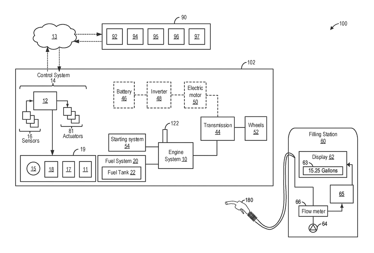
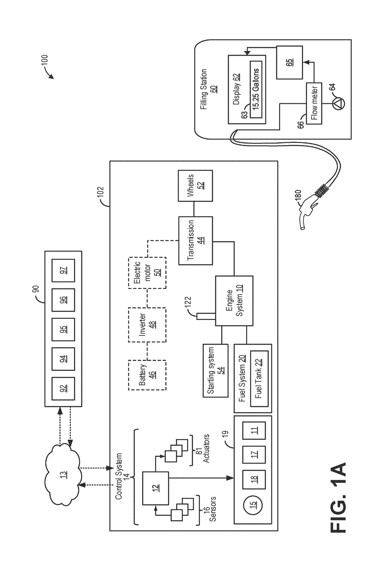
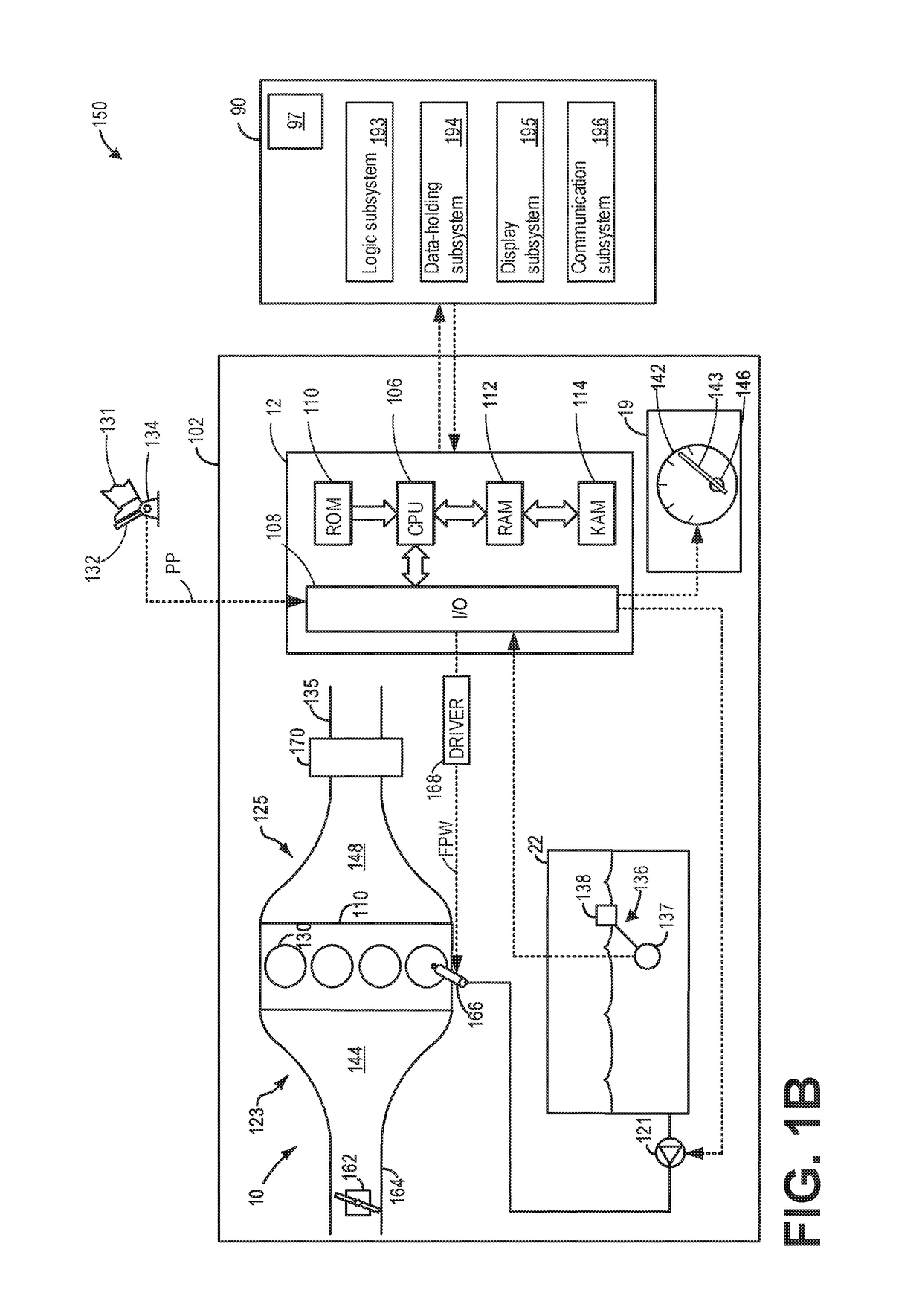
[0017]The present description relates to systems and methods for estimating fuel levels in a fuel tank of a fuel system, such as the example fuel system shown in FIG. 2. The fuel tank may include a fuel level indicator (FLI) sensor, which may comprise a float coupled to a variable resistor. The FLI sensor provides an indication of the fuel level to a controller of a vehicle, such as the vehicle system shown in FIGS. 1A and 1B, which may in turn be displayed to a vehicle operator via an in-dash display. However, when the FLI sensor fails, the fuel level provided to the vehicle operator may become inaccurate leading to refueling inefficiencies. In particular, overestimates of the fuel level may result in fuel exhaustion and vehicle stall, and underestimates of the fuel level may lead to excessive visits to refueling stations.

[0018]When degradation of the FLI sensor is detected, the fuel level of the fuel tank may instead be estimated based on an amount of fuel consumed during engine o...


PUM


Abstract

Methods and systems are provided for estimating fuel levels in a fuel tank. In one example, a method may comprise adjusting estimates of a fuel level in a fuel tank based on an amount of fuel added to the fuel tank during a refueling event. The amount of fuel added to the fuel tank may be provided by a vehicle operator via one or more of a dashboard user interface, a wireless device user interface, and a digital camera included within a user device.

Description

FIELD[0001]The present application relates to systems and methods for estimating fuel levels in a fuel tank.BACKGROUND / SUMMARY[0002]Accurately determining and indicating an amount of fuel contained within a fuel tank can often be critical for a vehicle operator. The fuel amount may be used to determine when and where the vehicle should be refueled prior to the fuel tank being emptied. A typical fuel tank utilizes a dedicated fuel level sensor, such as a floating sensor coupled to a variable resistor, to determine the amount of fuel remaining in the fuel tank.[0003]However, such fuel level sensors may be prone to sticking, malfunctioning, or decoupling from the vehicle powertrain control module, leading to inaccuracies in the outputs of the sensor. As such, estimates of the fuel level may become inaccurate, and an in-dash fuel gauge may provide an inaccurate or indeterminate fuel level to a vehicle operator. This may lead to the vehicle running out of fuel if the fuel gauge overestim...

Claims


Application Information

Patent Timeline
IPC IPC(8): G01F25/00B60K15/035B60K15/03
CPCG01F25/0061B60K15/03519G01F25/0069B60K2015/03019B60K2015/03514B60K2015/03197B60K2015/03203B60K2015/03217B60K2015/0319G01F9/00G01F25/20G01F25/22
Inventor AGHILI, MOHAMMAD R.DUDAR, AED M.YANG, DENNIS SEUNG-MAN
Owner FORD GLOBAL TECH LLC
Learn More