
Method and system to determine a range for a vehicle

a range and vehicle technology, applied in the field of vehicle range determination, can solve the problems of large residual volume, psychologically negative impact on the driver who is advised to refuel, and the burden of large fuel tanks, and achieve the effect of less sensitiv

Active Publication Date: 2018-10-30
SCANIA CV AB
View PDF10 Cites 0 Cited by
  • Summary
  • Abstract
  • Description
  • Claims
  • Application Information

AI Technical Summary

Benefits of technology

The present invention provides a method to estimate the range of a vehicle by using data related to the vehicle's base surface, such as the road slope, and the amount of fuel in the vehicle's tank. This allows for better fuel management to avoid stalling the vehicle. The transfer tank, which is smaller and less sensitive to fuel movements, acts as a buffer when fuel is not available, and it can be refilled when conditions allow. The method also involves estimating the amount of fuel remaining in the main tank based on the filling rate of the transfer tank, the size of the motor used to operate the fuel pump, the size of the battery used to power the motor, the size of the electric motor used to power the fuel pump, and the presence of a float in the main tank. The use of a float may not always be accurate, but the other methods provide a more accurate estimation of the remaining fuel amount.

Problems solved by technology

According to the above, at lower volumes and during certain driving conditions, there may be a risk of the fuel in the fuel tank not surrounding the inlet of the armature, with a risk of stalling as a consequence, and for this reason a minimum remaining volume in the fuel tank, at which fuel should be filled up again to avoid the risk of stalling, is often applied.
This means that vehicles with large fuel tanks are constantly burdened by a large extra volume, and therefore weight, which in practice may be used only very rarely or never.
This large residual volume may also have a psychologically negative impact on a driver who is advised to refuel, even though hundreds of liters of fuel may still remain in the vehicle's one or more petrol tanks.

Method used


Image

  • Method and system to determine a range for a vehicle
  • Method and system to determine a range for a vehicle
  • Method and system to determine a range for a vehicle

Examples


Embodiment Construction

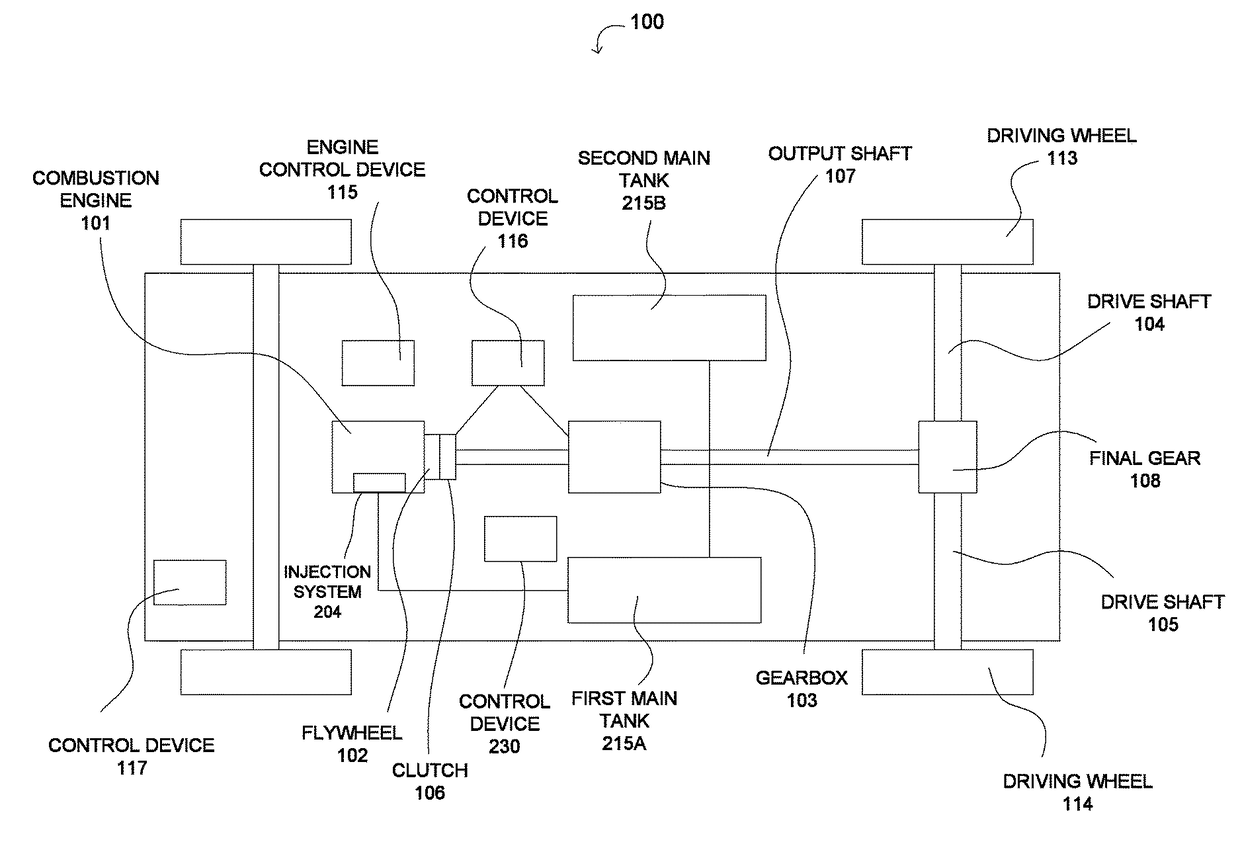
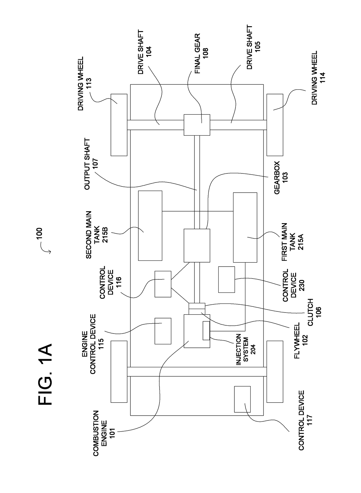
[0020]FIG. 1A schematically shows a driveline in a vehicle 100, according to an embodiment of the present invention. The vehicle 100, shown schematically in FIG. 1A, comprises a driveline with a combustion engine 101, which in a customary manner, via an output shaft on the combustion engine 101, usually via a flywheel 102, is connected to a gearbox 103 via a clutch 106. The combustion engine 101 is controlled by the control system 100 of the vehicle via an engine control device 115. Likewise, in the present example, the clutch 106 and the gearbox are controlled by a control device 116.

[0021]Further, an output shaft 107 from the gearbox 103 drives the driving wheels 113, 114 via a final gear 108, e.g. a customary differential, and the drive shafts 104, 105 connected to said final gear 108. FIG. 1A thus shows a powertrain of a specific type, but the invention is applicable to all types of powertrains, and also to all types of vehicles, as long as these are powered by a combustion engi...


PUM


Abstract

A method is provided for estimating a range for a vehicle, where the vehicle includes a combustion engine and a fuel supply system associated with the combustion engine. Vehicle also includes a first main tank for receiving fuel, and a first fuel pump for transfer of fuel from the first main tank to the fuel supply system. The method estimates a range for the vehicle based on data relating to the road ahead of the vehicle and a first measure of residual fuel in the first main tank. The method further controls a required fuel reserve based on the data relating to the road ahead of the vehicle.

Description

CROSS-REFERENCE TO RELATED APPLICATIONS[0001]This application is a national stage application (filed under 35 § U.S.C. 371) of PCT / SE2014 / 051419, filed Nov. 28, 2014 of the same title, which, in turn, claims priority to Swedish Application No. 1351446-8 filed Dec. 05, 2013 of the same title; the contents of each of which are hereby incorporated by reference.FIELD OF THE INVENTION[0002]The present invention relates to a method to determine a range for a vehicle. The invention also relates to a system and a vehicle, as well as a computer program and a computer program product, which implement the method.BACKGROUND OF THE INVENTION[0003]The present invention relates to fuel systems in vehicles, and in particular heavy goods vehicles such as trucks, buses and working machines. These types of vehicles are often relatively heavy and often also travel long distances. Overall, this entails a requirement that the vehicles be equipped with relatively large fuel tanks. For example, such vehicl...

Claims


Application Information

Patent Timeline
Patent Type & Authority Patents(United States)
IPC IPC(8): B60K15/06F02M37/00B60W40/12B60R16/023F02M37/08G07C5/08G06F19/00B60K15/03
CPCB60K15/061B60R16/023B60W40/12F02M37/0088F02M37/08G07C5/08Y02T10/84B60K2015/03144B60K2015/062B60K2350/1092B60W2550/143B60W2560/02B60W2530/209B60W2552/20B60K35/28B60K2360/174B60W10/30G06F9/44B60K15/06G01C21/3697B60K15/077
Inventor CEDFORS, DAN
Owner SCANIA CV AB
Learn More