Rack-mountable equipment with a high-heat-dissipation module, and transceiver receptacle with increased cooling

a technology of heat dissipation module and rackmountable equipment, which is applied in the direction of optics, instruments, optical light guides, etc., can solve the problems of excessive temperature in the transceiver, premature failure of the interconnection or other components in the electronics rack, and accelerated aging and/or other problems, so as to reduce the radiated stray electromagnetic radiation

Active Publication Date: 2018-10-30
SAMTEC
View PDF54 Cites 42 Cited by
  • Summary
  • Abstract
  • Description
  • Claims
  • Application Information

AI Technical Summary

Benefits of technology

[0014]To overcome the problems described above, preferred embodiments of the present invention provide an air-cooled heat sink that is located in the front bezel of a rack. Robust physical contact is provided between the heat sink and the heat generating components of the interconnection system, including, for example, the transceiver of an active optical cable. The robust physical contact and large heat dissipating surface of the heat sink provide a low impedance thermal path between the transceiver and the ambient environment. In addition to providing heat dissipation, the heat sink can also serve as an electromagnetic radiation shield, reducing radiated stray electromagnetic radiation outside of the rack enclosure.

Problems solved by technology

The inability to remove this heat can result in accelerated aging and / or premature failure of the interconnection or other components in the electronics rack.
However, as channel density and bandwidth increased, the heat generated by the transceiver increases, which can cause excessive temperatures in the transceiver.
Excessive temperatures can lead to premature failure and poor performance.
But these side holes do not effectively remove the heat within the passage 207 (FIG. 22) and thus do not effectively remove heat from the transceivers.
For interior transceivers in arrays 3×2 and bigger, the holes in the sides are not effective or adequate because the heat has to flow from an interior passage to an exterior passage with the sides holes.
If the heat in the passage 207 cannot be adequately removed, the transceivers can undergo accelerated aging and / or prematurely fail.

Method used


Image

  • Rack-mountable equipment with a high-heat-dissipation module, and transceiver receptacle with increased cooling
  • Rack-mountable equipment with a high-heat-dissipation module, and transceiver receptacle with increased cooling
  • Rack-mountable equipment with a high-heat-dissipation module, and transceiver receptacle with increased cooling

Examples


Embodiment Construction

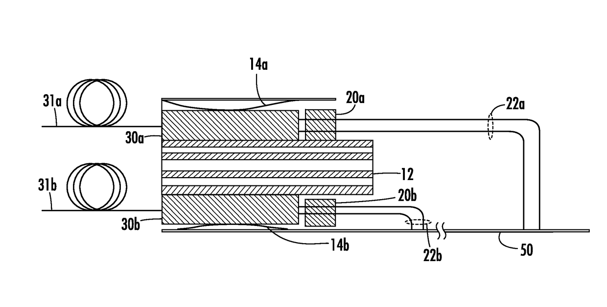
[0066]A preferred embodiment of the present invention provides a low-impedance thermal path between a transceiver and the ambient environment. Heat transfer to the ambient environment is provided by forced convective air flow across a heat sink. The heat sink is incorporated into the front bezel of a heat-dissipation module that can be mounted to an electronics rack. The heat sink can provide cooling for a plurality of transceivers. This contrasts with many prior art transceivers in which the heat sink is incorporated directly into the transceiver. The preferred embodiments of the present invention advantageously provide superior cooling for a large number of transceivers that are densely connected in an electronics rack.

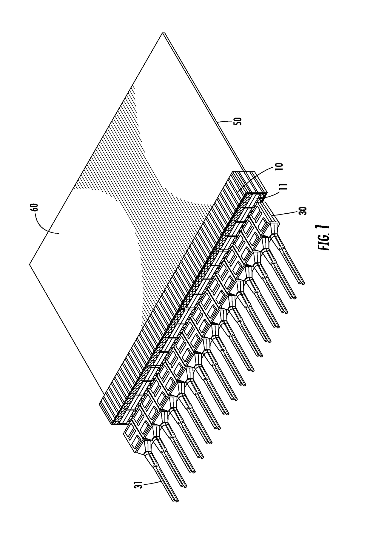
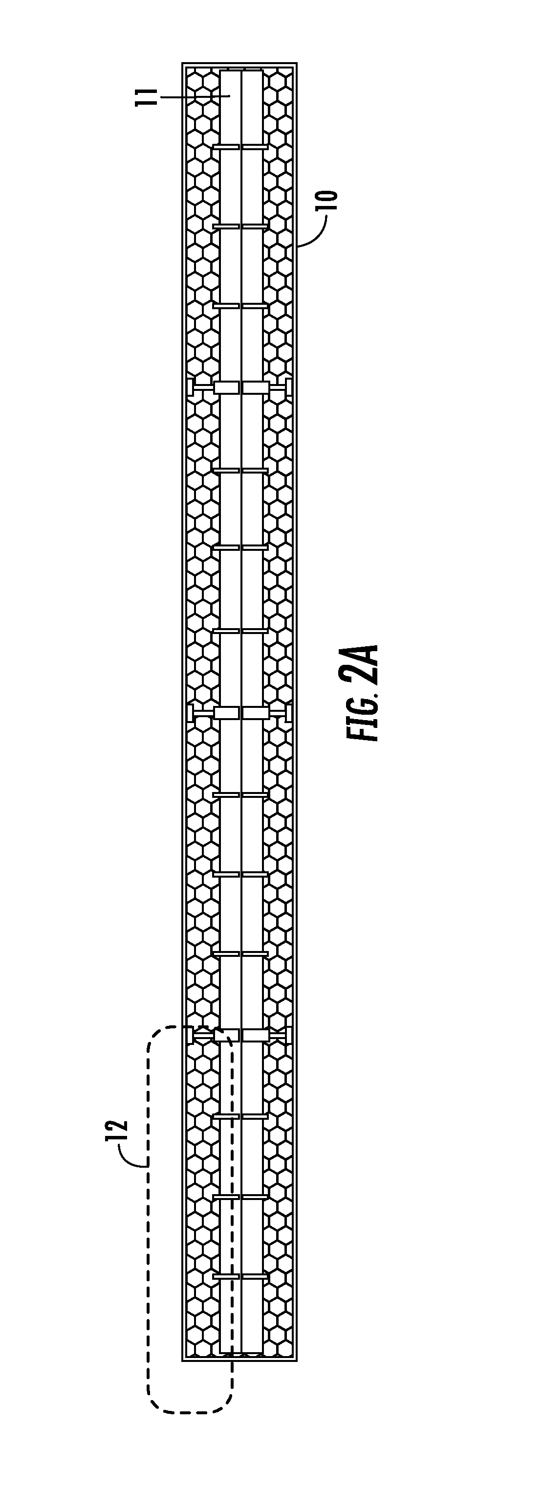
[0067]FIG. 1 shows a portion of rack mount 60. The rack mount 60 includes a heat-dissipation module 10, a printed circuit board (PCB) 50, a heat sink 12, a transceiver 30, and a cable 31. The transceiver 30 is preferably an optical transceiver, and the cable 31 is p...


PUM


Abstract

An electrical connector includes a heat dissipation module with a first end and a second end opposed to the first end and two receptacle connectors located at the second end. The first and second ends define a transceiver-mating direction such that, when a transceiver is inserted into the first end of the heat dissipation module in the transceiver-mating direction, the transceiver mates with one of the two receptacle connectors, and in the heat dissipation module, air flows parallel to the transceiver-mating direction between the first and second ends and flows between the two receptacle connectors.

Description

BACKGROUND OF THE INVENTION[0001]1. Field of the Invention[0002]The present invention relates to rack-mountable equipment with a heat-dissipation module and data interconnects, and also relates to a receptacle that receives an optical transceiver and that has increased cooling.[0003]2. Description of the Related Art[0004]Electronics racks are standard components for mounting a wide variety of electronic components and equipment in data, computing, and / or communication systems. Data centers typically have large numbers of racks, each filled with various pieces of electronic equipment, such as servers. A standard electrical rack has a 19″ width, which can support assemblies that mount into the rack with a width of 17.25″. Multiple assemblies can be mounted in each rack, one above the other. These assemblies typically are supported by a front bezel formed from cut outs in a flat piece of sheet metal that has clearance holes or slots along its edges to secure the bezel to the rack.[0005...

Claims


Application Information

Patent Timeline
Patent Type & Authority Patents(United States)
IPC IPC(8): G02B6/42G02B6/38
CPCG02B6/4268G02B6/4249G02B6/3897
Inventor ZBINDEN, ERIC J.HALL, III, THOMAS A.
Owner SAMTEC
Why Eureka
Try Eureka