Power line communication system and method of auto-commissioning system nodes

a communication system and power line technology, applied in the direction of power distribution line transmission, transmission, electroluminescent light sources, etc., can solve the problems of increasing system cost and general difficulty in service, and achieve the effect of reducing the cost of nodes, reducing the cost of device controller design, and high node coun

Active Publication Date: 2018-11-06
ABL IP HLDG
View PDF17 Cites 3 Cited by
  • Summary
  • Abstract
  • Description
  • Claims
  • Application Information

AI Technical Summary

Benefits of technology

[0007]In another aspect of the invention, the device control module will have a configuration that allows the use of inexpensive and mostly passive components. The configuration allows node costs to be substantially reduced and also allows for data rates high enough to provide real-time control of the device modules. (The device controller described herein can provide high baud rates of 500 Kbaud or more.) The cost effectiveness of the device controller design becomes particularly significant in applications, such as multi-panel OLED lighting fixtures, with high node counts.
[0008]The device controller also operates at low power so as to not adversely affect the efficacy of the system, and provides clean power to the device loads on the system so as to not cause noise problems or other unwanted effects such as optical flickering in lighting devices. The device controller further allows for the use of twisted pair wire in a differential communication mode avoiding the need for coaxial cables and helping to minimize both accepted and emitted EMI / RFI.

Problems solved by technology

However, such systems generally are not easily serviced when addressable components of the system need to be replaced or exchanged.
They also have another disadvantage, in that communication nodes used with the lighting elements typically involve relatively costly parts that, when multiplied over many addressable components, can add tremendous cost to the system.

Method used


Image

  • Power line communication system and method of auto-commissioning system nodes
  • Power line communication system and method of auto-commissioning system nodes
  • Power line communication system and method of auto-commissioning system nodes

Examples


Embodiment Construction

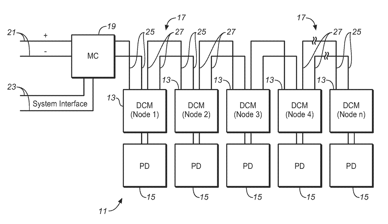
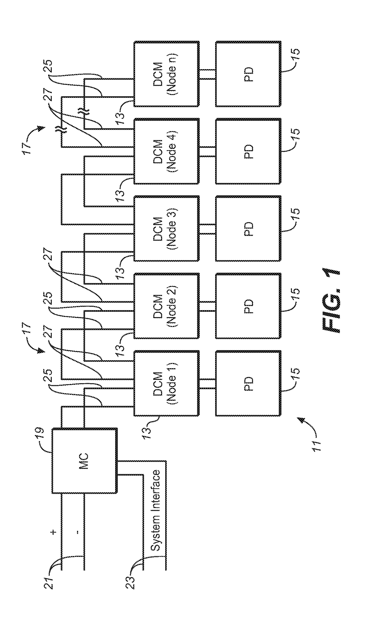
[0027]FIG. 1 illustrates the general configuration of a PLC system 11 in accordance with the invention wherein multiple device control modules or “nodes”13 associated with multiple peripheral devices 15 are connected to a common DC power line or buss 17. As hereinafter described, communication over the DC power line occurs by means of sequences of voltage pulses transmitted on the DC power line, wherein the voltage pulses represent serial digital data or control signals capable of being processed locally at any system node. A master controller 19 is suitably provided at the front end of the PLC system for use in powering-up of the system. The shown positive and negative wire inputs 21 to the master controller are from a source of DC power, most suitably at 12 volts DC; however, the master controller could alternatively include an AC-DC converter to accommodate an AC power feed. System control interfaces, for example dimmer switches of a lighting system, can also be connected to the ...


PUM


Abstract

A power line communication system and method permit auto-commissioning of multiple device control modules on a DC power line during the power up of the system. Device control modules associated with the peripheral devices are powered up sequentially and a unique address is assigned to each device controller when it is powered up. The device control modules have a unique circuit configuration that allows the use of inexpensive and mostly passive components. The cost effectiveness of the device controller design becomes particularly significant in applications, such as multi-panel OLED lighting fixtures, with high node counts.

Description

CROSS-REFERENCE TO RELATED APPLICATIONS[0001]This application claims the benefit of U.S. Provisional Patent Application No. 62 / 452,312 filed Jan. 30, 2017.GOVERNMENT RIGHTS[0002]This invention was made with Government support under U.S. Department of Energy Award No. DE-EE0007073. The Government has certain rights in the invention.BACKGROUND[0003]The present invention generally relates to methods for monitoring and controlling multiple devices connected to a common power line, and more particularly to a DC power line communication system. The invention has particular application to monitoring and controlling lighting elements or fixtures of a lighting system over a DC power buss to which the lighting elements or fixtures are connected. However, it will be appreciated that the invention will have other applications where it is desired to monitor and / or control multiple devices powered from a common low voltage DC power line.[0004]Power line communication (PLC) systems used for contro...

Claims


Application Information

Patent Timeline
Patent Type & Authority Patents(United States)
IPC IPC(8): H04B3/54H05B33/08H04B3/58H05B44/00
CPCH04B3/542H04B3/546H05B33/0803H04B3/548H04B3/58H05B47/185H05B45/36H05B45/32H05B45/375
Inventor SCOTT, JEFFREY MICHAELMIU, MICHAEL
Owner ABL IP HLDG
Why Eureka
Try Eureka