
Device for monitoring wear on overhead lines

a technology for overhead lines and wear detection, which is applied in the direction of force measurement by measuring optical property variation, force measurement apparatus, force/torque/work measurement, etc., can solve the problem that the force measurement system should have high mechanical sturdiness with respect to overload, and achieve the effect of reducing structural size, high mechanical sturdiness, and minimal air resistance in the travel direction

Active Publication Date: 2018-11-13
HOTTINGER BALDWIN MESSTECHNIK GMBH
View PDF6 Cites 0 Cited by
  • Summary
  • Abstract
  • Description
  • Claims
  • Application Information

AI Technical Summary

Benefits of technology

The invention is about a system that measures the force between an electricity collector and an overhead line to help determine if there is any wear or damage to the line. The system should be strong and durable enough to withstand heavy usage, and should be as small and airtight as possible to minimize interference during movement.

Problems solved by technology

The force measurement system should have high mechanical sturdiness with respect to overload, as encountered when the overhead line freezes.

Method used


Image

  • Device for monitoring wear on overhead lines
  • Device for monitoring wear on overhead lines
  • Device for monitoring wear on overhead lines

Examples


Embodiment Construction

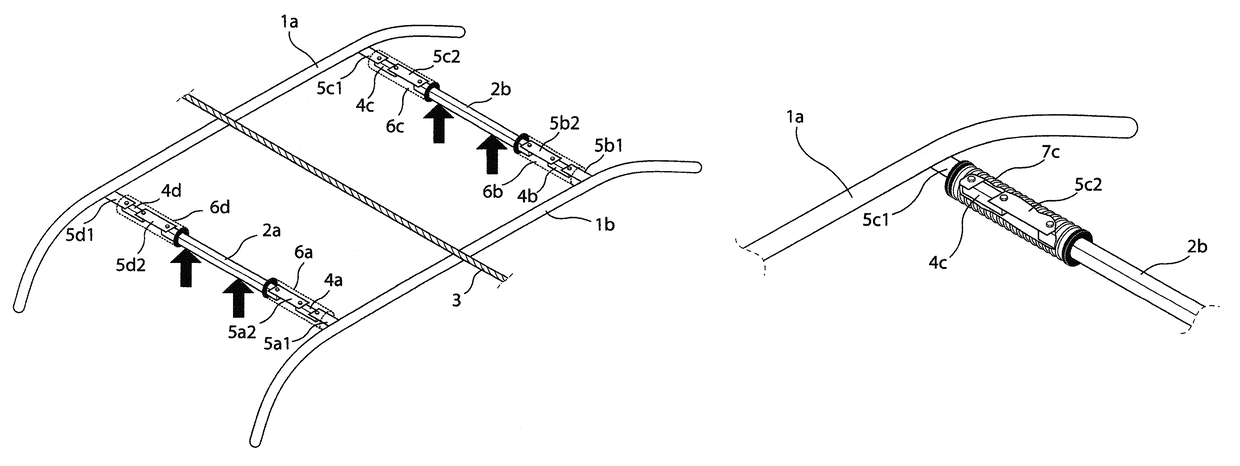
[0034]As shown in FIG. 4, the dual current collector according to the state of the art includes two contact bars (1a, 1b) and two connection bars (2a, 2b) connected therewith, with the contact bars (1a, 1b) being arranged in the operating mode at a right angle to the overhead line (3), and with the connection bars (2a, 2b) being arranged in parallel relation thereto. Press-on rods, coupled with the connection bars (2a, 2b) but not shown, urge the contact bars (1a, 1b) upon the overhead line (3). The arrow tips of the 4 upwardly directed force arrows point to the coupling points of the not shown press-on rods.

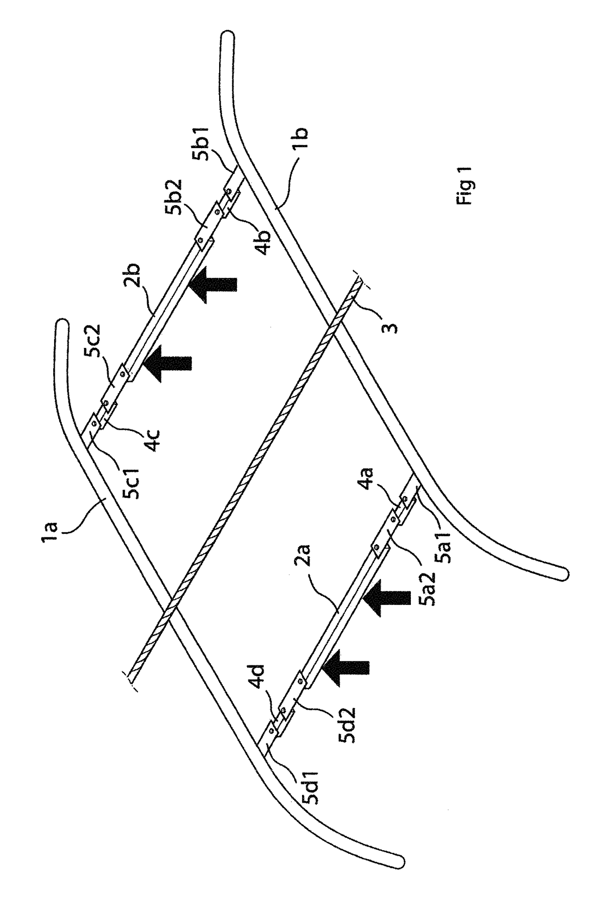
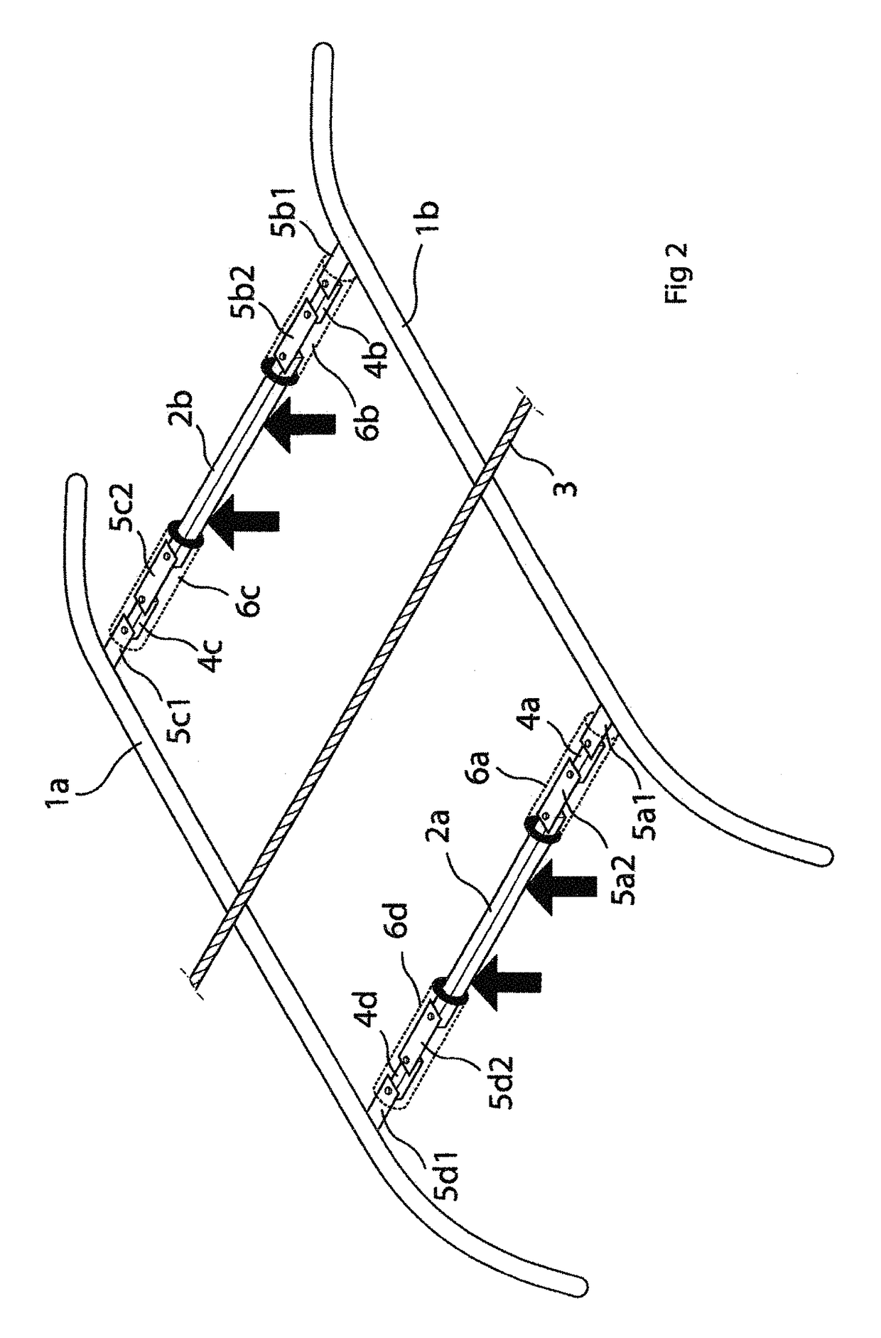
[0035]FIG. 1 shows a first embodiment of a device for monitoring wear on overhead lines, including a bar-shaped force transducer (4a-4d) arranged at each end portion of the two connection bars (2a, 2b) and extending in parallel relation to the overhead line (3), i.e. in travel direction. As a result, only the relatively small end faces of the bar-shaped force transducers (4a-4d)...


PUM


Abstract

A device for measuring force and for monitoring wear on overhead lines includes a force-measuring system which includes two contact bars which, in an operating state, are oriented at a right angle to an overhead line to be monitored, and two connection bars, which, in the operating state, are oriented parallel to the overhead line. A bar-shaped force transducer is fastened to each end portion of the two connection bars and each of the bar-shaped force transducers extends in an axial direction of the respective connection bar.

Description

CROSS-REFERENCES TO RELATED APPLICATIONS[0001]This application is the U.S. National Stage of International Application No. PCT / DE2014 / 000571, filed Nov. 7, 2014, which designated the United States and has been published as International Publication No. WO 2015 / 067235 and which claims the priority of German Patent Application, Serial No. 10 2013 018 819.9, filed Nov. 7, 2013, pursuant to 35 U.S.C. 119(a)-(d).BACKGROUND OF THE INVENTION[0002]The invention relates to a device for monitoring wear on overhead lines for electrically-operated rail vehicles which include a current collector with a pair of contact bars.[0003]The force with which a pair of contact bars of a current collector is pressed against the overhead line has an impact on both wear of the overhead line and wear of the contact bars. Measuring the contact force, and in particular measuring momentary changes in the contact force enables inference about damage to the overhead line or to the contact bars.[0004]Various device...

Claims


Application Information

Patent Timeline
IPC IPC(8): G01L1/24B60L5/20B60L5/22G01L5/10G01D5/353
CPCG01L1/246B60L5/20G01L5/107G01D5/3537B60L5/22
Inventor VIEL, WOLFGANG
Owner HOTTINGER BALDWIN MESSTECHNIK GMBH
Learn More