Galvanically isolated hybrid contactor

a hybrid contactor and galvanic isolation technology, applied in the direction of electromagnetic relay details, electrical apparatus, electromagnetic relays, etc., can solve the problems of large size, inefficiency, high design and production costs of solid-state electronic circuit breakers, etc., to reduce the degradation of inventive devices, reduce heat dissipation from inventive devices, and inexpensive semiconductors

Active Publication Date: 2018-11-20
ASTRONICS ADVANCED ELECTRONICS SYST
View PDF56 Cites 13 Cited by
  • Summary
  • Abstract
  • Description
  • Claims
  • Application Information

AI Technical Summary

Benefits of technology

[0010]The hybrid contactor includes a series-parallel arrangement of mechanical contacts with solid state devices. This increases the switching capacity of the mechanical contacts, and maintains galvanic isolation when open.
[0013]One advantage of the disclosed subject matter is that it allows for galvanic isolation between input and output when the contactor is off.
[0014]Another advantage of the disclosed subject matter is that it provides arc-less switching, reducing degradation of the inventive device.
[0015]Yet another advantage of the disclosed subject matter is that an inexpensive semiconductor may be utilized.
[0016]Yet another advantage of the disclosed subject matter is that heat dissipation from the inventive device is greatly reduced.
[0017]Yet an additional advantage of the disclosed subject matter is elimination of relay contact failure.

Problems solved by technology

In such scenarios, solid state electronic circuit breakers are large, inefficient, and very costly to design and produce.

Method used


Image

  • Galvanically isolated hybrid contactor
  • Galvanically isolated hybrid contactor
  • Galvanically isolated hybrid contactor

Examples


Embodiment Construction

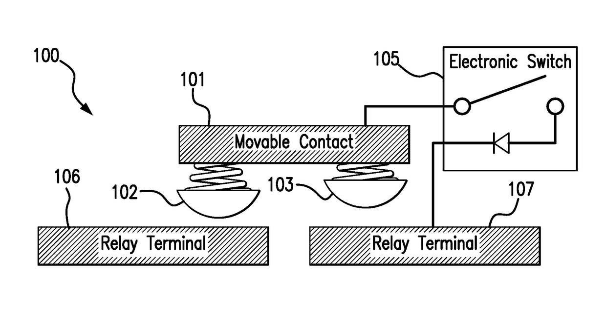
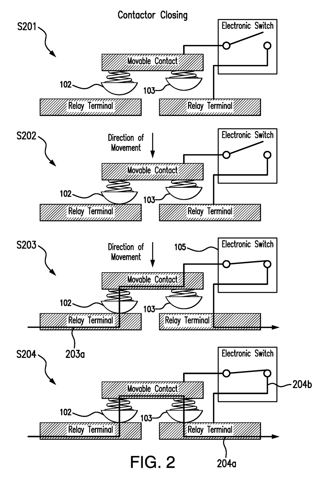
[0023]FIG. 1 is a schematic diagram of one embodiment of the inventive hybrid contactor 100. A movable contact 101 includes two mechanical contacts 102 and 103 used in series. Mechanical contacts 102 and 103 form a double gap contactor, with a single activating electromagnetic actuator. Mechanical contacts 102 and 103 are mechanically arranged in accordance with the invention such that, upon activation of the magnetic contact closure device, contact 102 closes shortly before the second of contact 103.

[0024]The second mechanical contact 103 is electronically arranged in a parallel circuit 104 to an electronic switch 105. Electronic switch 105 may include one or more semiconductor devices, such as an SCR, FET, transistor, or any other suitable semiconductor device.

[0025]In an illustrative sequence, closure of the first contact 102 causes power to be applied to the electronic switch 105. The electronic switch 105 begins conducting current in parallel 104 with the second contact 103. Sh...


PUM


Abstract

A hybrid contactor device that provides the ability to use the device with both AC and DC circuits is provided. The hybrid contactor includes a series-parallel arrangement of mechanical contacts with solid state devices, increasing the switching capacity of the mechanical contacts, and maintains galvanic isolation when open. The hybrid contactor includes two mechanical contacts, and is arranged so that one contact closes shortly before the other. The second contact forms a parallel circuit with an electronic switch.

Description

FIELD OF THE DISCLOSURE[0001]The subject matter of the present disclosure generally relates to circuit control devices, and more particularly relates to a hybrid contactor built with both mechanical and semiconductor switching elements.BACKGROUND OF THE DISCLOSURE[0002]U.S. application Ser. No. 14 / 044,303, titled “Virtual Electronic Circuit Breaker” and commonly owned with the present patent application, discloses a hybrid contactor-based virtual circuit breaker with an electrical relay and control circuit, and is incorporated by reference herein in its entirety.[0003]Control devices for circuits, such as switches, are important in many electrical applications. For instance, various circuit breaker designs that are useful in numerous applications have been previously developed and disclosed.[0004]In current aerospace power distribution systems, electrical loads are fed through a thermal circuit breaker and a power relay connected in-series, in order to provide load and wire protecti...

Claims


Application Information

Patent Timeline
Patent Type & Authority Patents(United States)
IPC IPC(8): H01H9/20H01H49/00H01H51/30H01H47/00
CPCH01H47/007H01H51/30H01H49/00H01H9/542H01H50/546
Inventor POTTER, FREDERICK J.MILLS, PATRICK
Owner ASTRONICS ADVANCED ELECTRONICS SYST
Why Eureka
Try Eureka