Connector system for rapid assembly and disassembly of panels and other members

a technology of connecting rods and panels, which is applied in the direction of sheet joining, fastening means, connections, etc., can solve the problems of difficult to create close enough tolerances to make a very tight joint without glue in wood related products, and practical to try and make dry fitting joints, etc., to achieve the effect of small movement and same strength

Inactive Publication Date: 2018-11-27
KOCH JON RUSSELL
View PDF74 Cites 26 Cited by
  • Summary
  • Abstract
  • Description
  • Claims
  • Application Information

AI Technical Summary

Benefits of technology

[0015]The instant invention overcomes the problem of the large insertion and removal force that prevents the use of long dovetail connections in connecting large panels or members, such as those employed in ready to assemble, or knock down, furniture, stud walls or structures employing panels that are relatively large in comparison to the connectors. The connector system of the instant invention allows male and female connector parts with dovetail sides to be drawn tightly together and also disengaged with only a relatively small movement. Multiple dovetail male and female connectors can be used along the joint between two components, such as two panels, and will draw the two joined components together to substantially the same degree as a conventional dovetail slot and will achieve substantially the same strength as a dovetail slot without requiring the relatively large movement required for insertion or retraction of a dovetail member extending along at least most of the length of a joint.
[0019]The converging angles on the side of the elements of the connector system of the instant invention substantially allow frictionless insertion and travel to the point where the male and female mating surfaces fully engage. At the point of engagement of the male / female surfaces there is considerable friction. Ribs on the sides of one version, but not all versions, of the male connector can either cut into the side walls of the female cavity or are slightly deformed themselves to achieve a strong non-flexing rigid connection. In other embodiments, the exterior shape of the mating surface of the male connectors will substantially match the interior shape of the female connector profile.

Problems solved by technology

Creating close enough tolerances to make a very tight joint without glue in wood related products is very difficult.
Because of the immense friction between the mating surfaces of sliding dovetails it is not practical to try and make dry fitting joints that can be easily disassembled.

Method used


Image

  • Connector system for rapid assembly and disassembly of panels and other members
  • Connector system for rapid assembly and disassembly of panels and other members
  • Connector system for rapid assembly and disassembly of panels and other members

Examples


first embodiment

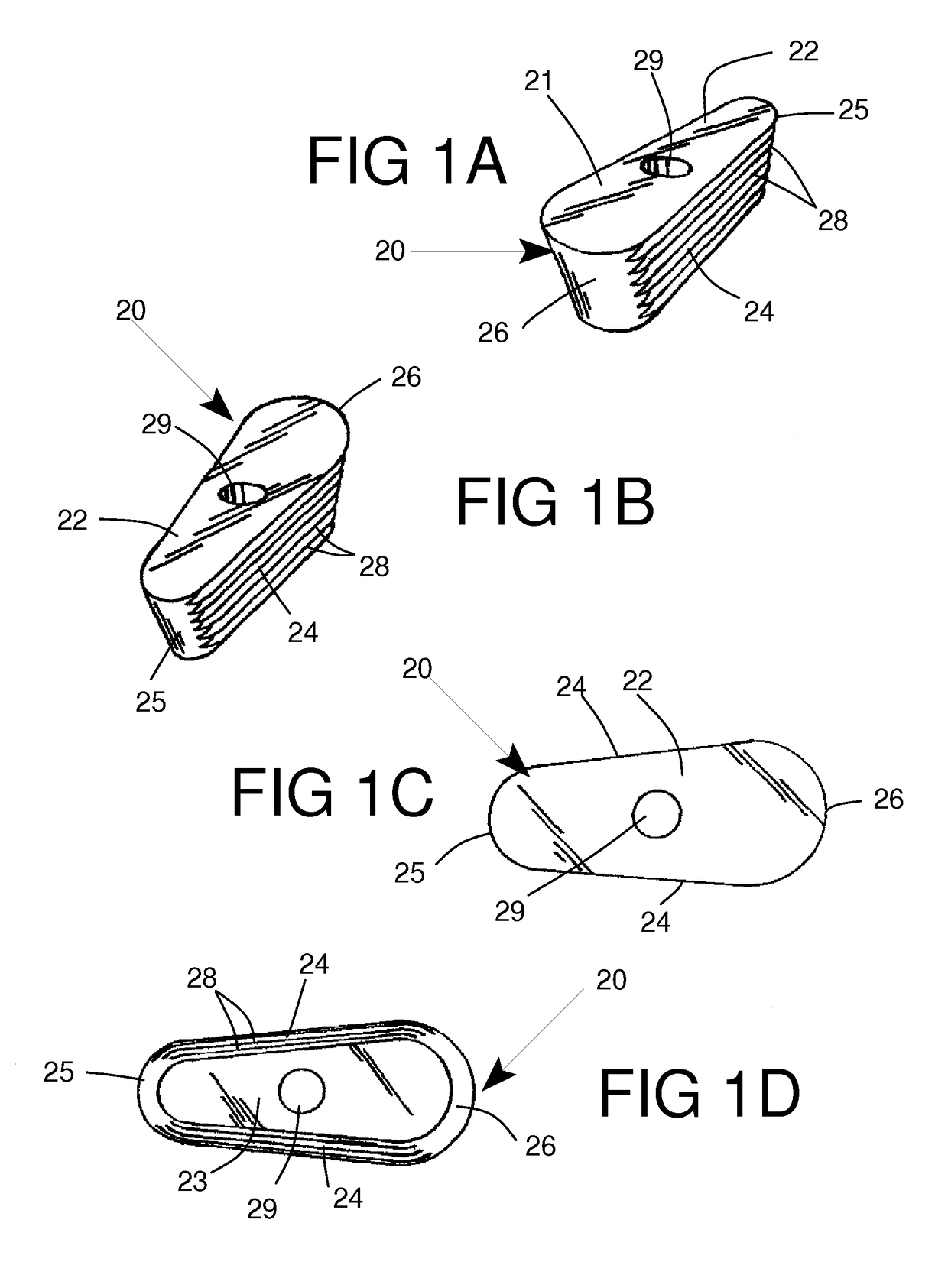
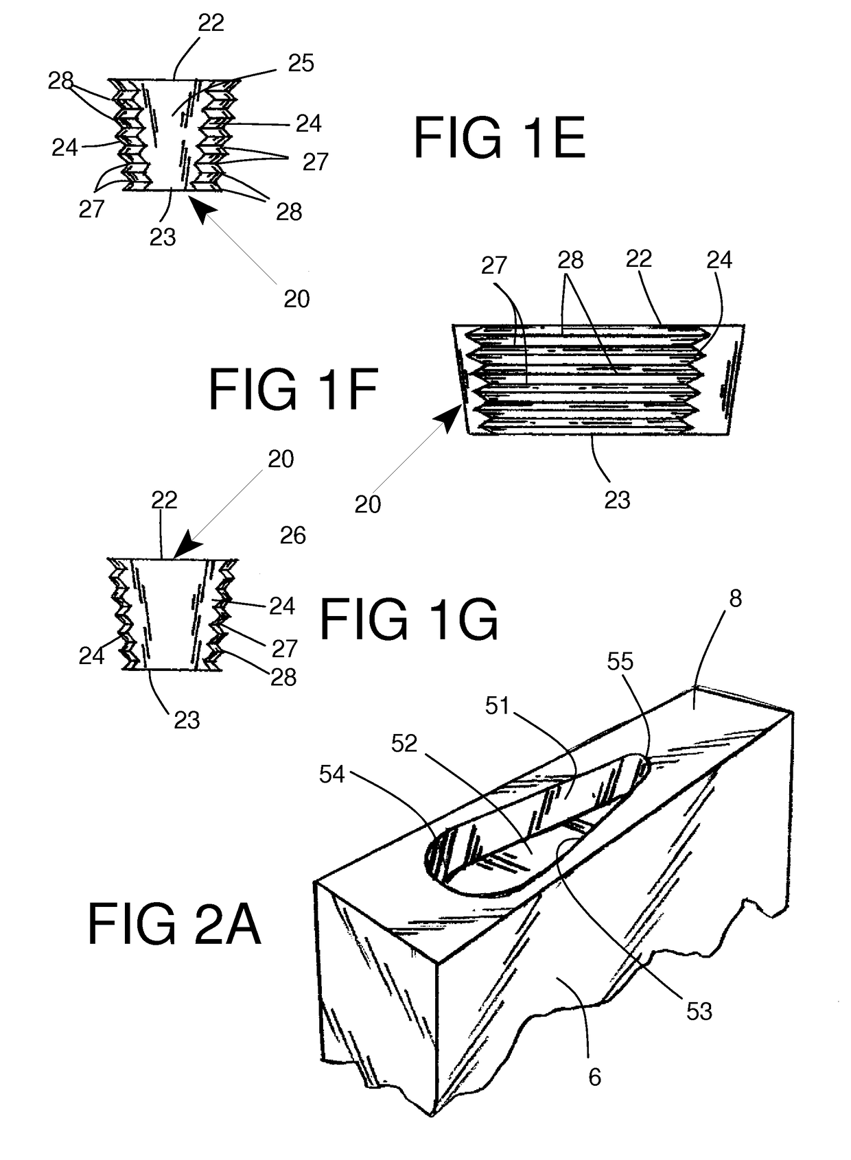
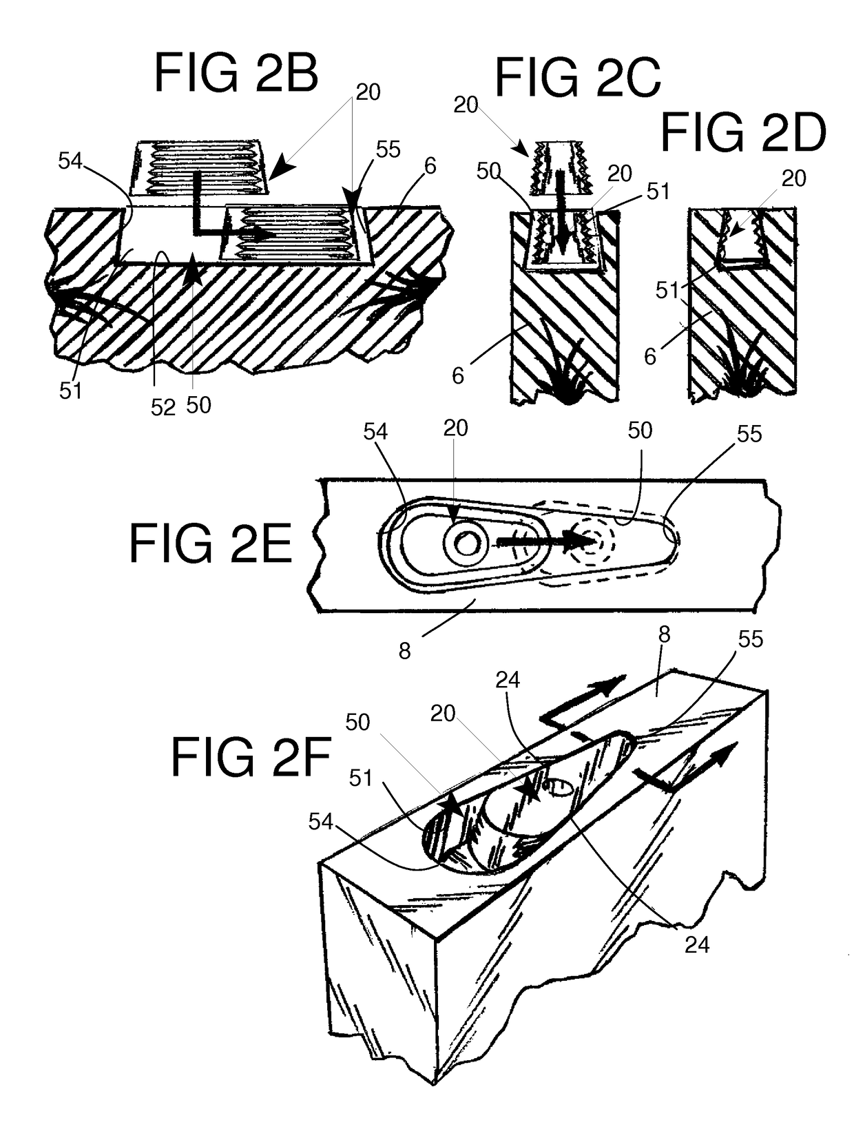
[0066]Both the male connectors 20, 30 and female connectors 50 according to this invention have a tapered or converging body 21 with sides that converge from one end toward another end and which are slanted or inclined between top and bottom faces or inner and outer faces or surfaces. FIGS. 1A and 1B show the double taper configuration of a male connector 20 representative of this invention. Opposite side or side edges 24 of the male connector 20 are tapered or inclined in two directions. The female connector or recessed female profile 50 will have corresponding side walls 51 that are tapered at approximately the same angles as the male connector sides 24. It should be understood, however, that in this embodiment the length of the female connector or female recess or profile 50 is greater than the length of the male connector 20 and the maximum width of the female connector or profile 50 will be greater than the maximum width of the male connector 20. In other embodiments, to be dis...

second embodiment

[0072]FIGS. 3A-3G and 4A-H show a male connector 30, which includes the basic features of the first male connector 20, but also includes additional components. Male connector 30 has the same basic double taper shape as male connector 20 with opposed sides 34 converging from rear end 36 towards the narrower forward end or nose 35 of the tapered connector body 31. Opposed side edges 34 are also inclined between the wider upper or exposed face 32 and the narrower lower face 32. There are fewer deeper channels 37 and protruding ribs 38 forming the fluted sides 34, but these ribs 38 extend generally between the front end 35 and the rear end 36 as in the previous embodiment. The mounting hole 39 extending through the body 31 is oblong instead of being circular, and this larger mounting hole permits the male connector 30 to be slightly adjusted relative to a fastener 60. This adjustment will not only allow more freedom in initially placing the male connector 30, but it will also allow some...


PUM


Abstract

A connector system for joining panels or other components together includes male connectors and female connector recessed profiles. The male connectors are attachable to one panel or component and the female connector profiles can be formed in or attached to another panel or component. The male connector has a tapered body with dovetail side edges extending between a narrower leading end and a wider trailing end. The female connector profile has a footprint with a wider open entry section and a narrower closed anchoring section. Dovetail side walls extend between the entry and anchoring sections. The connectors are small, and multiple male and female connectors are used on joining panels. The connector system can be used in ready to assemble furniture, stud walls and other assemblies and are especially suited for use in wood based members of composite construction.

Description

CROSS REFERENCE TO PRIOR CO-PENDING APPLICATION[0001]This application claims the benefit of prior co-pending Provisional Patent Application 62 / 002,199 filed on May 23, 2014.BACKGROUND OF THE INVENTION[0002]Field of the Invention[0003]This invention is related to formation of tight, close fitting joints between two members such as panels of the type used in ready to assemble furniture or members used in stud walls and especially for attaching or joining wood based components. This invention is also related to male and female dovetail connectors or connector profiles.[0004]Description of the Prior Art[0005]In wood related products a balanced distribution of force with equal strength between mating portions of two members to be joined together is preferred. A dovetail slot that is routed along an entire edge of a panel, with a good fitting dovetail inserted along the entire length of the edge of the panel, has so much bearing surface between the two parts that the thinner wall on the o...

Claims


Application Information

Patent Timeline
Patent Type & Authority Patents(United States)
IPC IPC(8): F16B5/00F16B12/34F16B12/22F16B5/01F16B5/06
CPCF16B5/0052F16B5/01F16B12/22F16B12/34F16B5/0614Y10T403/7075
Inventor KOCH, JON RUSSELL
Owner KOCH JON RUSSELL
Why Eureka
Try Eureka