Longitudinal displacement unit with braking rollers

a technology of longitudinal displacement unit and braking roller, which is applied in the direction of linear bearings, bearings, shafts and bearings, etc., can solve the problems of insignificant increase in resistance to longitudinal displacement unit displacement under torque, so as to achieve the effect of substantially maintaining the low-friction displacement function and relatively high elasticity of additional rolling members

Inactive Publication Date: 2005-06-07
GKN DRIVELINE DEUTSCHLAND GMBH
View PDF9 Cites 27 Cited by
  • Summary
  • Abstract
  • Description
  • Claims
  • Application Information

AI Technical Summary

Benefits of technology

[0005]The present invention provides an improved longitudinal displacement unit wherein the ball cage, when free of torque, retains its position. In one embodiment, in addition to the torque transmitting balls, the ball cage contains rolling members which include an elastic material and which are held between the profiled sleeve and the profiled journal, so as to be able to roll. The rolling members are positioned between the profiled sleeve and the profiled journal, so as to be radially pre-tensioned and, during the transmission of torque, remain largely free from circumferential forces. There is thus generated a small amount of resistance against axial displacement at the ball cage, which resistance remains effective even if there is no torque at all and if the load is removed

Problems solved by technology

On the other hand, the friction generated by the rollers is so low that the resistance to displace

Method used


Image

  • Longitudinal displacement unit with braking rollers
  • Longitudinal displacement unit with braking rollers
  • Longitudinal displacement unit with braking rollers

Examples


first embodiment

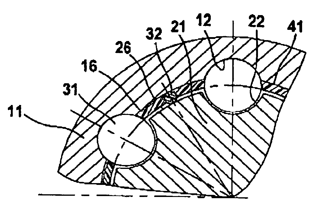
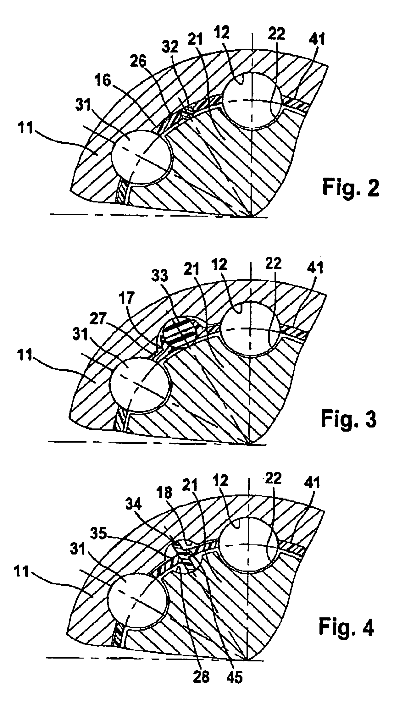
[0026]FIG. 2 shows a device according to FIG. 1 in a first embodiment in a cross-sectional view. It shows the profiled sleeve 11 with the first ball grooves 12, the profiled journal 21 with the second ball grooves 22 and the torque transmitting balls 31 which are positioned in pairs of ball grooves 12, 22 which are held by the ball cage 41 in the same circumferential distribution. Between each two torque transmitting balls 31, there are positioned additional balls 32 with a smaller diameter which are also clipped into recesses in the ball cage 41. The ball cage 41 can be made of an elastic material. The balls 32 are made of an elastic material and are positioned under radial pretension between the profiled sleeve 11 and the profiled journal 12, and roll on the inner cylindrical face 16 of the profiled sleeve 11 and on the outer cylindrical face 26 of the profiled journal 21. The balls 32 can also be in the form of a cylindrical rod or barrel-shaped rollers. The balls 32 can have an ...

second embodiment

[0027]FIG. 3 shows a longitudinal displacement unit according to FIG. 1 in a Identical details have been given the same reference numbers as in FIG. 2. Between each two torque transmitting balls 31, there can be seen additional balls 33 which are made of an elastic material and which, in a radially pretensioned condition, run in additional grooves 17 in the profiled sleeve 11 and on the outer cylindrical face 27 of the profiled journal 12. As a result, when the torque transmitting balls 31 are torque-loaded, the ball members 33 are kept free from circumferential forces and do not take part in the transmission of torque. The grooves 17 have a large radius of curvature as compared to the rolling member 33 radius. Again, the rolling member 33 can be in the form of a ball, rod, or barrel-shaped roller.

third embodiment

[0028]FIG. 4 shows a longitudinal displacement unit according to FIG. 1 in a Details which are identical to those shown in FIG. 2 have been given the same reference numbers. Between each two torque transmitting balls 31 in this embodiment, radially pretensioned disc members 34 made of an elastic material are inserted into the ball cage 41. The disc members 34 run in additional grooves 18, 28 which, in this case, comprise a circular cross-sectional shape similar to the first and second ball grooves 12, 22. Indeed, the grooves 18, 28 can be identical to the inner and / or outer ball grooves 12, 22. During the transmission of torque, the discs 34, because they are tiltably supported in the cage 41, are kept free from circumferential forces and thus from the transmission of torque. In other words, the discus have an oscillating axis of rotation. The discs 34 can be kept in the cage 41 by knobs 45 engaged in central spherical caps 35.

[0029]In each of the embodiments, the number and locati...


PUM


Abstract

A longitudinal displacement unit for a shaft assembly includes a profiled sleeve (11) with first ball grooves (12), a profiled journal (21), second ball grooves (22), balls (31) which are arranged in groups in pairs of first and second ball grooves (11, 22), and a ball cage (41) which is positioned between the profiled sleeve (11) and the profiled journal (21) and fixes the balls (31) in their axial position relative to one another. The ball cage (41) contains elastic rolling members which are positioned between the profiled sleeve (11) and the profiled journal (21), so as to be radially pre-tensioned and which, during the transmission of torque, remain largely free from circumferential forces.

Description

TECHNICAL FIELD[0001]The invention relates to a longitudinal displacement unit for a shaft assembly for torque transmitting purposes. The unit includes a profiled sleeve with circumferentially distributed, longitudinally extending first ball grooves, a profiled journal with circumferentially distributed, longitudinally extending second ball grooves, balls which are arranged as groups in pairs of first and second ball grooves, and a ball cage which is positioned between the profiled sleeve and the profiled journal and fixes the balls in their axial position relative to one another. The ball cage is axially displaceable between two end stops in the outer joint part and / or on the inner joint part.BACKGROUND OF THE INVENTION[0002]In telescopic shafts, if the profiled sleeve and the profiled journal are displaced relative to one another under torque, the balls in the inner and outer ball grooves roll substantially without any sliding friction. As a result, the balls and the ball cage wit...

Claims


Application Information

Patent Timeline
IPC IPC(8): F16D3/02F16C3/02F16C3/035F16D3/06
CPCF16D3/065F16C3/035F16C29/04
Inventor WELSCHOF, HANS-HEINRICH
Owner GKN DRIVELINE DEUTSCHLAND GMBH
Why Eureka
Try Eureka