Steering gear having a fixed bearing and a floating bearing for a screw pinion

a technology of screw pinion and fixed bearing, which is applied in the direction of bearing unit rigid support, gearing, manufacturing tools, etc., can solve the problems of low service life of bearing configuration, and development of nois

Active Publication Date: 2014-03-11
ROBERT BOSCH AUTOMOTIVE STEERING
View PDF24 Cites 32 Cited by
  • Summary
  • Abstract
  • Description
  • Claims
  • Application Information

AI Technical Summary

Benefits of technology

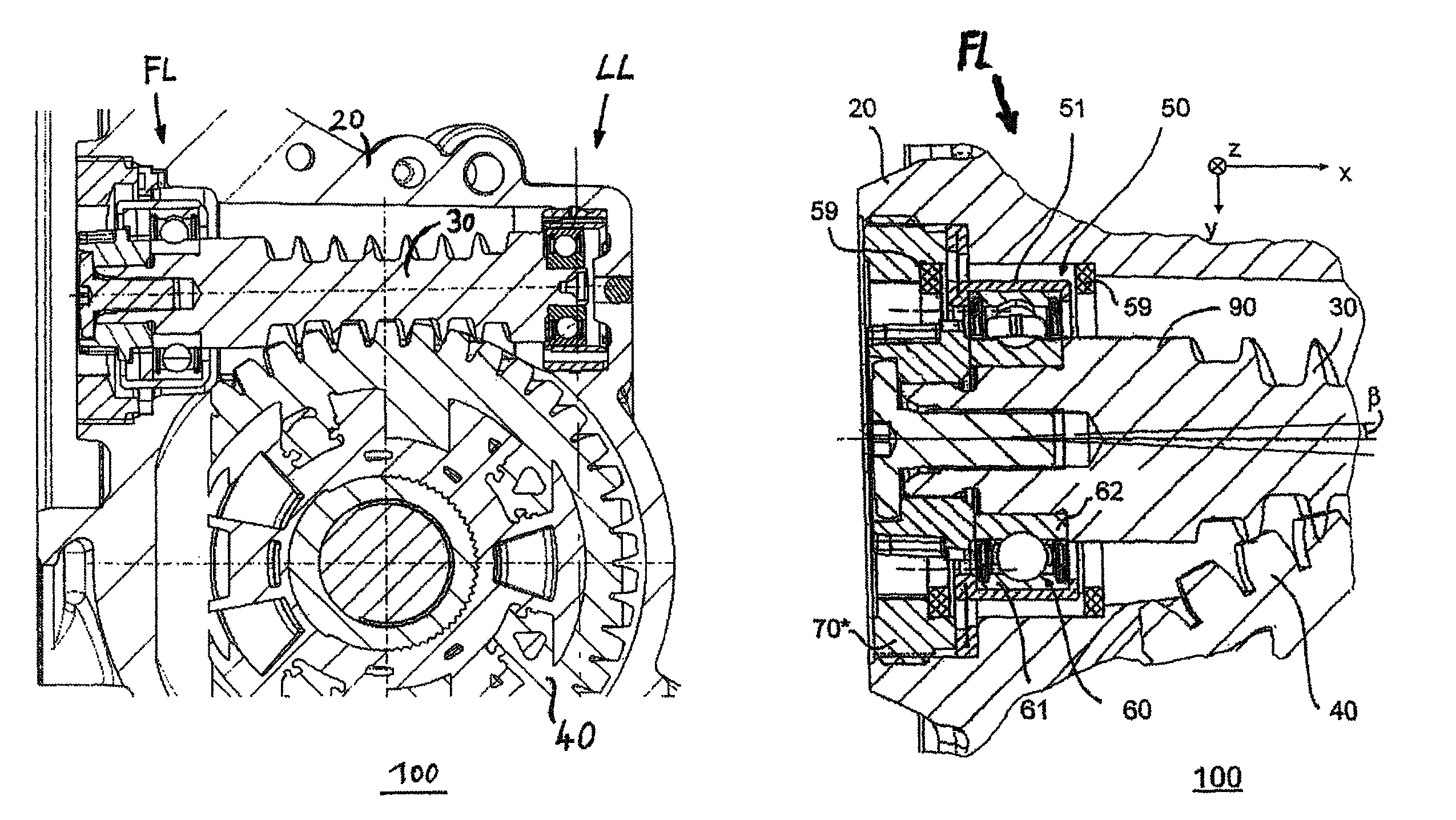
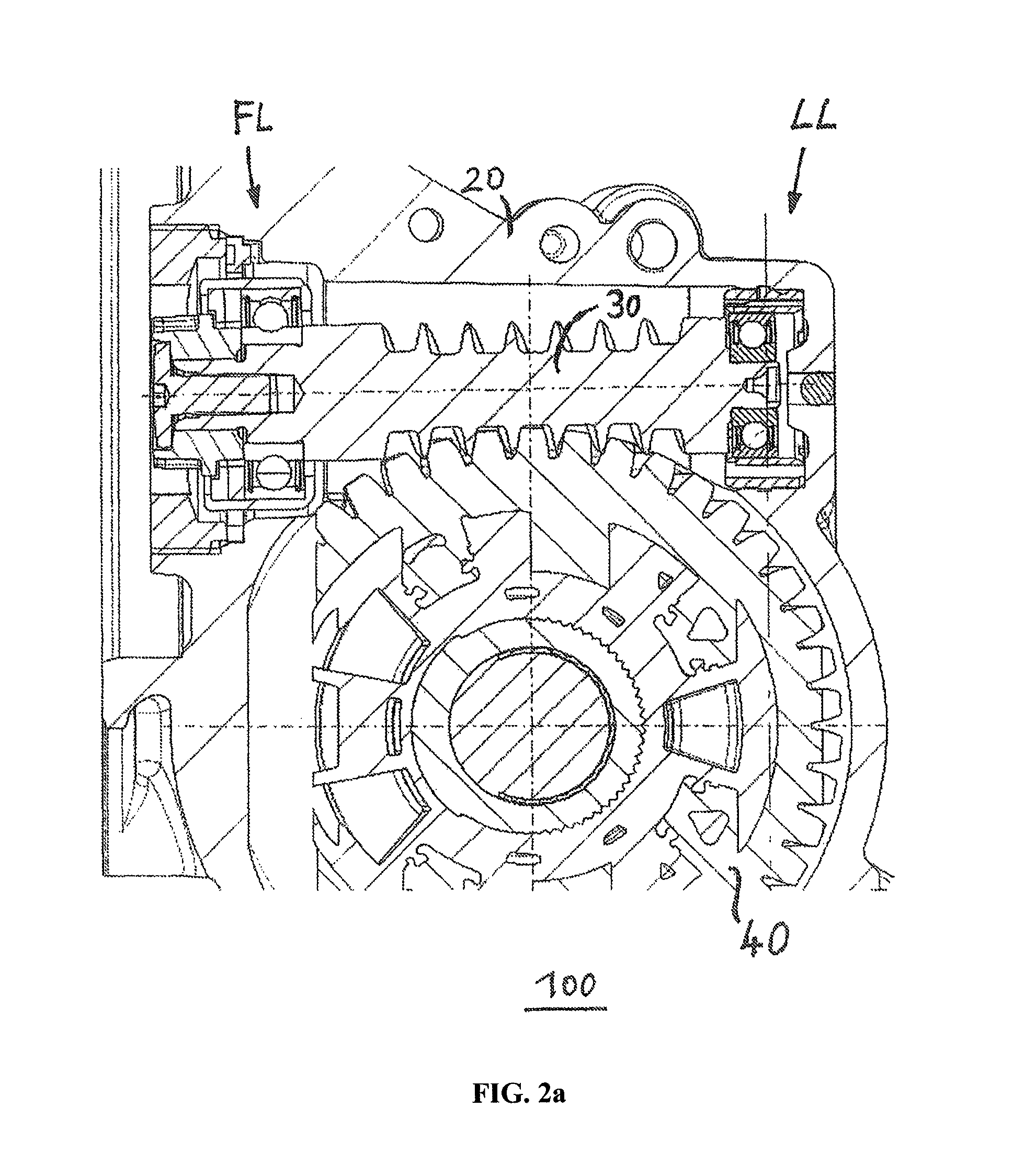
[0011]On the fixed bearing side, a shaft bearing configuration is thus proposed in which the rolling bearing is not installed directly in the housing section, but in which a mounting for the rolling bearing is provided, which comprises two sections and, by means of openings, exhibits elasticity that is created between the sections and reduces the noise of the shaft bearing configuration. One section of the mounting has an annular shape and is assembled with one of the bearing rings (outer or inner ring) of the rolling bearing. The other section has a disk-shaped design and can be pivoted relative to the annular section because of the openings. This disk-shaped section is installed in the housing section when the annular section receives or encloses the outer ring of the rolling bearing, or the disk-shaped section is connected to the shaft when the annular section carries the inner ring. Both alternatives are based on the same principle, which is to say to install an elastic mounting for the rolling bearing on the fixed bearing side, the mounting being installed either between the rolling bearing and the housing, or between the rolling bearing and the shaft. In other words: the openings provided in the mounting lend definable elasticity to the mounting, whereby at least the section of the mounting which holds the outer ring or inner ring of the rolling bearing (for example, of a ball bearing) is able to carry out a movement, and preferably a slight pivoting movement.
[0013]The mounting provided on the fixed bearing side preferably has a multi-piece design, wherein the annular section is produced as a first piece from a first material, and more particularly from a soft sheet metal, and the disk-shaped section is produced as a second piece from a second material, and more particular from spring steel sheet. The mounting can thus also be produced by assembling several parts or sections, wherein these should, in each case, be produced from materials which are optimal for the function of the respective part or section. The disk-shaped section, which should exhibit certain elasticity, is produced in particular from spring steel sheet, for example, in the shape of a spring washer. All parts or sections can be produced cost-effectively from corresponding sheet metal.
[0016]As a result of these measures, defined elasticity is introduced in the floating bearing, noise is limited, and the engagement of the helical pinion with the helical gear is improved.
[0018]Both measures, both on the fixed bearing side and on the floating bearing side, act together in a combinatorial way in a particularly advantageous manner. They can be implemented cost-effectively, can be quickly adapted to the design and performance-related requirements of the steering gear (material selection for fixed bearing parts or sections and / or adaptation of the spring characteristic for the floating bearing) and considerably reduce noise. Moreover, toothing engagement is considerably improved.
[0024]Moreover, it is advantageous to provide the housing section of the steering system with at least one elastic damping element against which the axially movable mounting strikes. This additionally dampens the seat of the spring washer in the axial direction.

Problems solved by technology

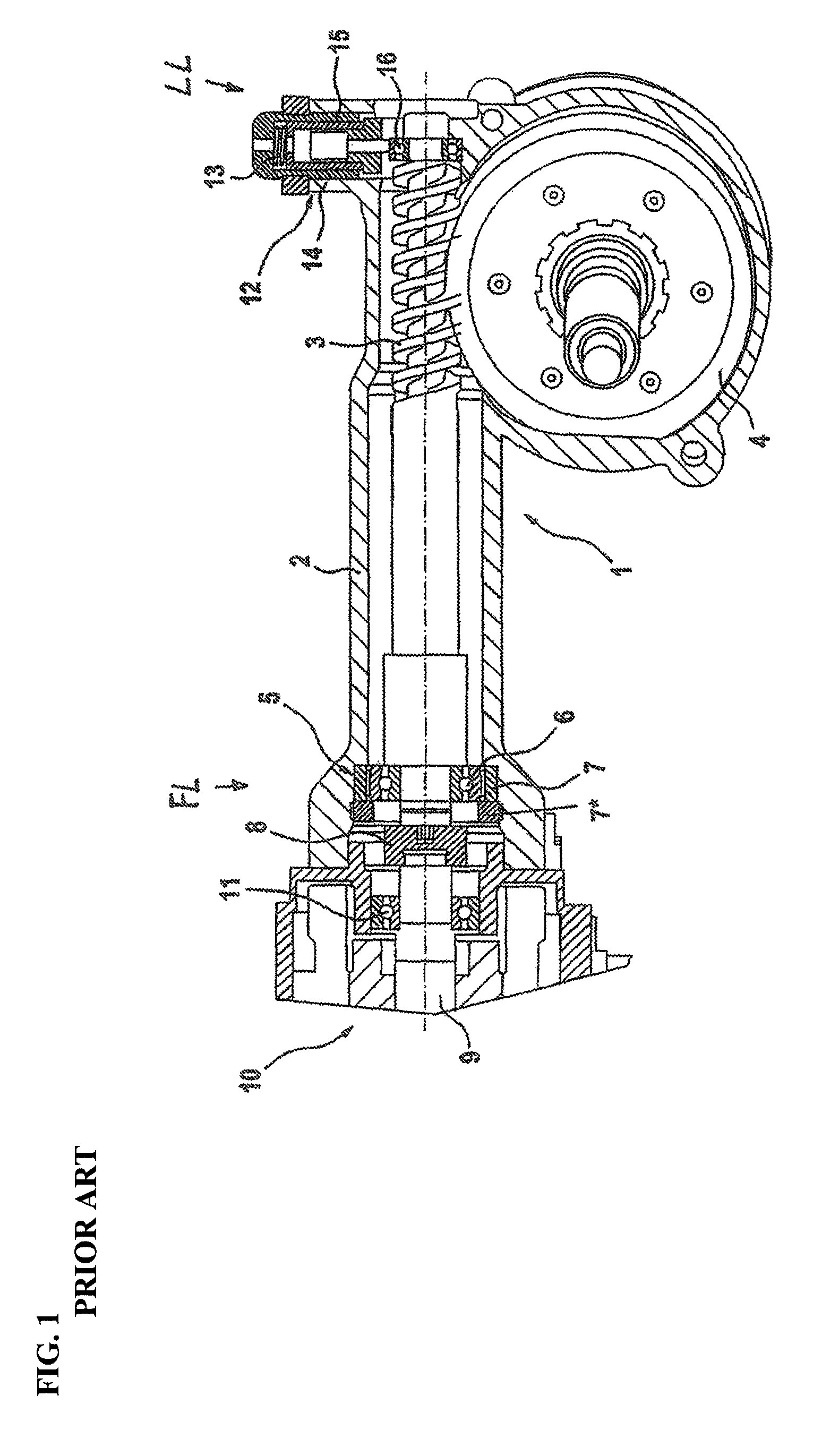
However, it has been shown such a known design may also create noise at the shaft bearing 5, wherein the noise can be eliminated here only conditionally through the use of an expensive specialty bearing.
However, these solutions are complex to implement and have relatively large play, which in turn results in the development of noise, notably during load changes (changes in steering).
Moreover, these shaft bearing configurations are susceptible to temperature fluctuations and the service life thereof is not long.

Method used


Image

  • Steering gear having a fixed bearing and a floating bearing for a screw pinion
  • Steering gear having a fixed bearing and a floating bearing for a screw pinion
  • Steering gear having a fixed bearing and a floating bearing for a screw pinion

Examples


fifth embodiment

[0062]As a fifth embodiment, FIGS. 7a and 7b show a two-part mounting 51*, which in addition to a crucible-shaped section or section part 51b* contains a non-disk-shaped but lug-shaped section or section part 51a*. This saves material. Moreover, the mounting can be attached or assembled in the housing by way of through bores 55*, which are provided in the lug-shaped section 51a*. FIGS. 8a to 8c show related cross-sectional views.

[0063]The lug-shaped section 51a* is produced from a first sheet metal or sheet metal material, which is to say spring steel sheet. The crucible-shaped section 51b* is produced from a second sheet metal which is softer than the first sheet metal. In order to connect the two parts 51a* and 51b*, the first section part 51a* contains several apertures 56* or holes through which material of the crucible-shaped part 51b*, which is made of soft sheet metal WB, is pushed on one side and then compressed on the opposite side, for example to form rivets, as is illustr...

sixth embodiment

[0065]FIGS. 10a, b show details of an alternative connecting technique and a mounting 51** produced therewith, the mounting again comprising a disk-shaped section.

[0066]So as to produce this mounting 51**, according to the invention, apertures 56** are likewise provided in the first sheet metal, however protruding regions of the crucible-shaped section part 51b* are then placed through these apertures so as to then be formed on the opposite side, whereby a positive fit and / or non-positive fit likewise connects the two section parts 51a**, 51b** to each other, wherein, for example, a closed rivet head or an open rivet head or tubular rivet is formed.

[0067]When producing such mountings, and more particularly when connecting the two section parts or halves, it is also possible for the two parts to be connected by means of press joining or clinching, or by means of punch riveting.

[0068]Moreover, it is possible to connect the two section parts using additional rivets and / or additional sc...


PUM

PropertyMeasurementUnit
angleaaaaaaaaaa
shapeaaaaaaaaaa
lug shapeaaaaaaaaaa

Abstract

A steering gear comprises a shaft bearing configuration which comprises a mounting which is installed in a housing section of the steering gear and has openings that enable a pivoting movement by an annular section of the mounting which is assembled with a first rolling bearing, and the mounting comprises a disk-shaped section, which is provided with the openings and relative to which the annular section can be pivoted, wherein the annular section is either assembled with the outer ring of the first rolling bearing and the disk-shaped section is attached to the housing section, or the annular section is assembled with the inner ring of the first rolling bearing and the disk-shaped section is attached to the shaft.

Description

[0001]This is a Continuation of U.S. National Stage of PCT / EP2010 / 069344 Filed Dec. 10, 2010.BACKGROUND OF THE INVENTION[0002]The invention relates to a steering gear according to the preamble of claim 1 and to a steering system equipped therewith. The invention in particular relates to a steering gear which is designed as a helical gear mechanism or a worm gear mechanism for an electric power steering system.[0003]A steering gear of the type in question in the form of a helical gear mechanism for use in an electric power steering system is known from DE 101 61 715 A1. FIG. 1 shows the known helical gear mechanism 1, which is designed as a worm gear mechanism comprising a housing 2, in which a worm 3 and a worm gear 4 are disposed, wherein the worm 3 is connected by means of a coupling 8 to the drive shaft 9 of an electric drive motor 10, the shaft being mounted in a bearing 11. In this known design, the worm shaft is mounted in a shaft bearing 5, which comprises a ball bearing 6 in...

Claims


Application Information

Patent Timeline
Patent Type & Authority Patents(United States)
IPC IPC(8): F16C27/00F16H35/00
CPCB62D5/0409F16C35/045F16C23/06F16C2380/27F16C2361/61F16H2057/0213F16C27/04F16H25/24Y10T29/49908Y10T74/1966F16H55/24F16C35/07
Inventor FUECHSEL, DENNISHAFERMALZ, JENS
Owner ROBERT BOSCH AUTOMOTIVE STEERING
Why Eureka
Try Eureka