MEMS flow sensor

a flow sensor and flow meter technology, applied in the direction of volume/mass flow measurement, measurement devices, instruments, etc., can solve the problems of limited device performance, inefficient sensing in only a single plane, and omnidirectional thermal convection, so as to improve the sensitivity of thermal flow sensors, increase flow impedance, and high flow impedance

Active Publication Date: 2018-11-27
ACEINNA INC
View PDF9 Cites 6 Cited by
  • Summary
  • Abstract
  • Description
  • Claims
  • Application Information

AI Technical Summary

Benefits of technology

[0007]The micro flow channel is of a size which improves the sensitivity of the thermal flow sensor since a greater percentage of the measured liquid or gas is heated in comparison with a much larger conventional flow channel in which the heater power remains constant. The micro flow channel also increases the flow impedance to thereby permit much less fluid to flow into the sensor channel. The micro channel is suitable for micro liter per minute or nano liter per minute liquid flow rates.
[0008]The MEMS micro flow channel sensors can be used in a bypass to a main flow channel to measure only a portion of the bulk flow. The high flow impedance of the micro flow channel prevents contaminants from entering the bypass channel since momentum to carry particles into the bypass channel is greatly reduced. The use of a micro flow channel in a bypass arrangement is particularly applicable where high sensitivity and contamination immunity is required. Such applications include natural gas metering, mass air flow for internal combustion engines and exhaust gas recirculation for gasoline and diesel engines.
[0010]Each silicon substrate may include one-half of a flow channel such that when the two substrates are joined or fused together, the completed flow channel is formed. In another embodiment, only one substrate contains the flow channel and the other substrate which could be either glass or silicon provides a cap over the channel. The heater and one or more temperature sensors can be configured inside or outside the flow channel and can be disposed on one or more walls of the flow channel or as loops or coils around the channel. Forming a heater and temperature sensor on more than one plane of the flow channel walls increases the magnitude of the sensor signal since heat is sensed over a larger surface area. The increase in thermal signal leads to higher sensitivity and increases the sensor dynamic range to thereby increase the power efficiency. When the width of the flow channel is larger than the height, temperature sensors and heaters located on the sidewalls are usually unnecessary as the signal gain will be minimal. The wall structures around the flow channel can have etched cavities or thinned walls to reduce heat loss through the silicon material. A thin layer of silicon nitride or other insulating material can be coated over the heater and temperature sensor surfaces to prevent oxidation.

Problems solved by technology

The sensing of temperature in only one plane limits the performance of the device.
Thermal convection is omnidirectional and sensing in only a single plane is inefficient.

Method used


Image

  • MEMS flow sensor
  • MEMS flow sensor
  • MEMS flow sensor

Examples


Embodiment Construction

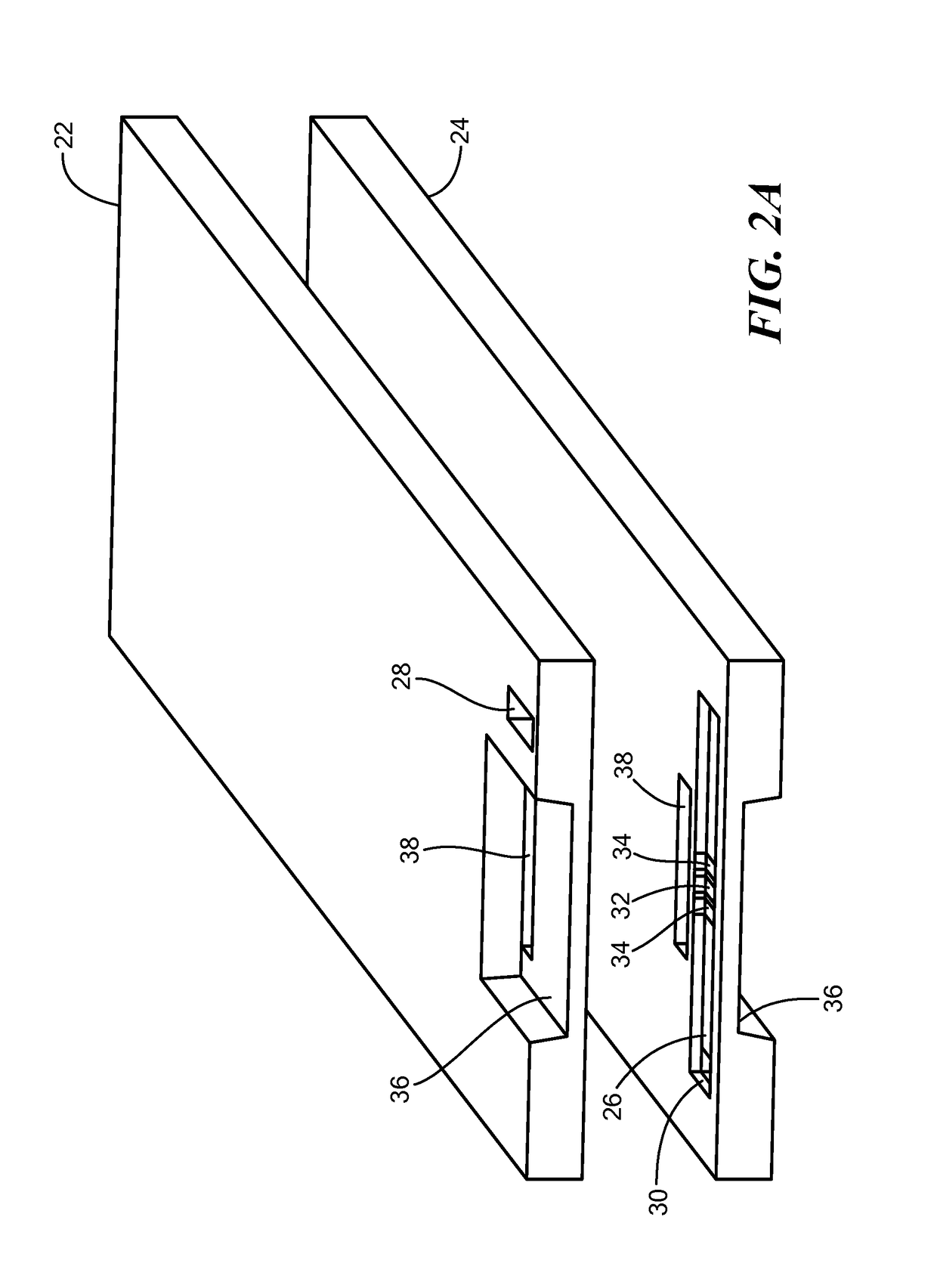
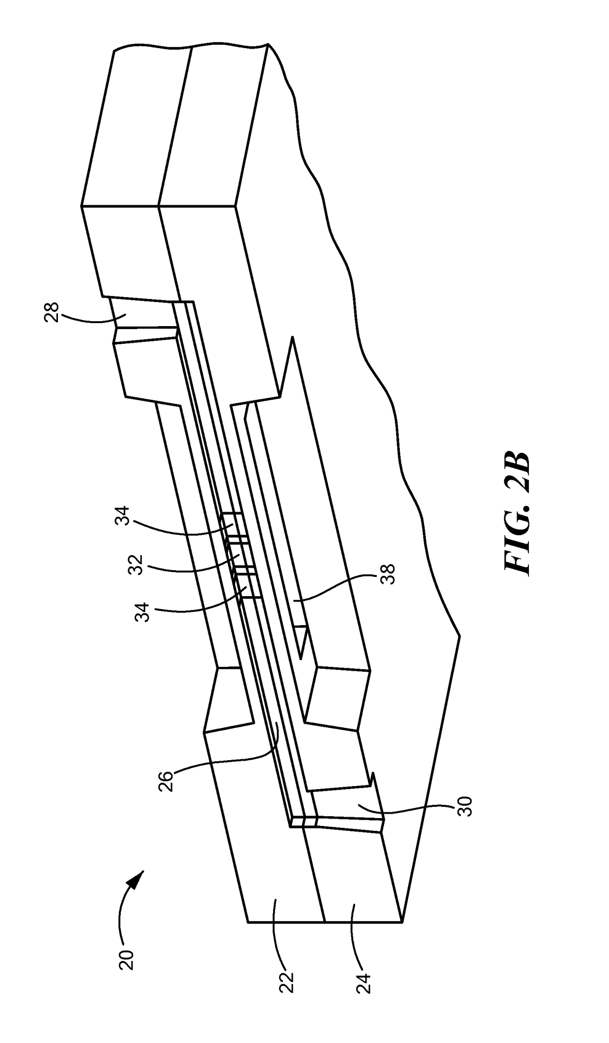
[0025]One embodiment of the invention is shown in FIGS. 2A and 2B. A body 20 is formed by silicon substrates or structures 22 and 24 which are bonded or fused together. A flow channel 26 is formed in the body and having at one end an opening 28 formed in substrate 22 and at the opposite end an opening 30 formed in substrate 24. These openings serve as inlet or outlet holes for the fluid which is caused to flow through the flow channel 26. A heater 32 and temperature sensors 34 are etched along the perimeter of the flow channel 26 on each wall thereof to form a complete loop or coil around the inside of the flow channel. Trenches 36 are provided in each substrate 22 and 24 on each side of the flow channel to reduce the thickness of the bulk material of the substrates and thereby reduce heat losses and consequent signal losses. At least one etched opening 38 is provided through the substrates 22 and 24 for the same purpose of providing thinned sidewalls of the flow channel.

[0026]Elect...


PUM


Abstract

A MEMS flow sensor is provided having a micro flow channel etched in a silicon structure composed of two silicon substrates bonded or fused together. A heater and one or more temperature sensors are, in one embodiment, disposed around the perimeter of the flow channel and outside of the channel. In another embodiment, a heater and one or more temperature sensors are respectively disposed outside the flow channel at the top and bottom of the channel. In further embodiments, a heater and one or more temperature sensors are located inside the flow channel on one or more surfaces thereof or around the inside perimeter of the channel. The flow sensors in accordance with the invention are preferably fabricated using wafer scale fabrication techniques.

Description

STATEMENT REGARDING FEDERALLY SPONSORED RESEARCH OR DEVELOPMENT[0001]N / ABACKGROUND OF THE INVENTION[0002]Micro-Electro-Mechanical Systems (MEMS) based thermal sensors are known in many different configurations. A basic MEMS flow sensor includes a heater and at least one temperature sensor in the near vicinity to detect heat fluctuation as fluid moves over the heater and temperature sensor(s). The rate of fluid movement over the heater and temperature sensor(s) can be used to determine flow rate.[0003]Existing MEMS flow sensors utilize a heater and temperature sensors on a single plane inside the flow channel on a diaphragm or suspended bridge. One known form of flow sensor is shown in FIG. 1A in which a heater 10 and temperature sensors 12 are supported on a diaphragm or membrane 14 which is disposed in a flow channel 16. Another known version of a flow sensor is shown in FIG. 1B in which a heater 10A and temperature sensors 12A are formed in a silicon plate 18 which is placed in a ...

Claims


Application Information

Patent Timeline
Patent Type & Authority Patents(United States)
IPC IPC(8): G01F1/684G01F1/692
CPCG01F1/6847G01F1/692G01F1/6845
Inventor ZHAO, YANGSILPACHAI, OHLANMAN, FRANCISZHAO, ZHENGXIN
Owner ACEINNA INC
Why Eureka
Try Eureka